H3C Technologies H3C S12500 Series Switches User Manual
Page 274
258
Item Network
requirements
IP multicast routing
•
Enable IP multicast routing on the P device.
•
Enable IP multicast routing on the public network on PE 1, PE 2, and PE 3.
•
Enable IP multicast routing in VPN instance a on PE 1, PE 2, and PE 3.
•
Enable IP multicast routing in VPN instance b on PE 2 and PE 3.
•
Enable IP multicast routing on CE a1, CE a2, CE a3, CE b1, and CE b2.
IGMP
•
Run IGMPv2 on VLAN-interface 20 of PE 1.
•
Run IGMPv2 on VLAN-interface 40 of CE a2, VLAN-interface 50 of CE a3, and
VLAN-interface 60 of CE b2.
PIM
•
Enable PIM-SM on all interfaces of the P device.
•
Enable PIM-SM on all public and private network interfaces of PE 1, PE 2 and PE 3.
•
Enable PIM-SM on all interfaces of CE a1, CE a2, CE a3, CE b1, and CE b2.
•
Configure Loopback 1 of P as a C-BSR and a C-RP for the public network (to work for
all multicast groups).
•
Configure Loopback 1 of CE a2 as a C-BSR and a C-RP for VPN a (to work for all
multicast groups).
•
Configure Loopback 2 of PE 3 as a C-BSR and a C-RP for VPN b (to work for all
multicast groups).
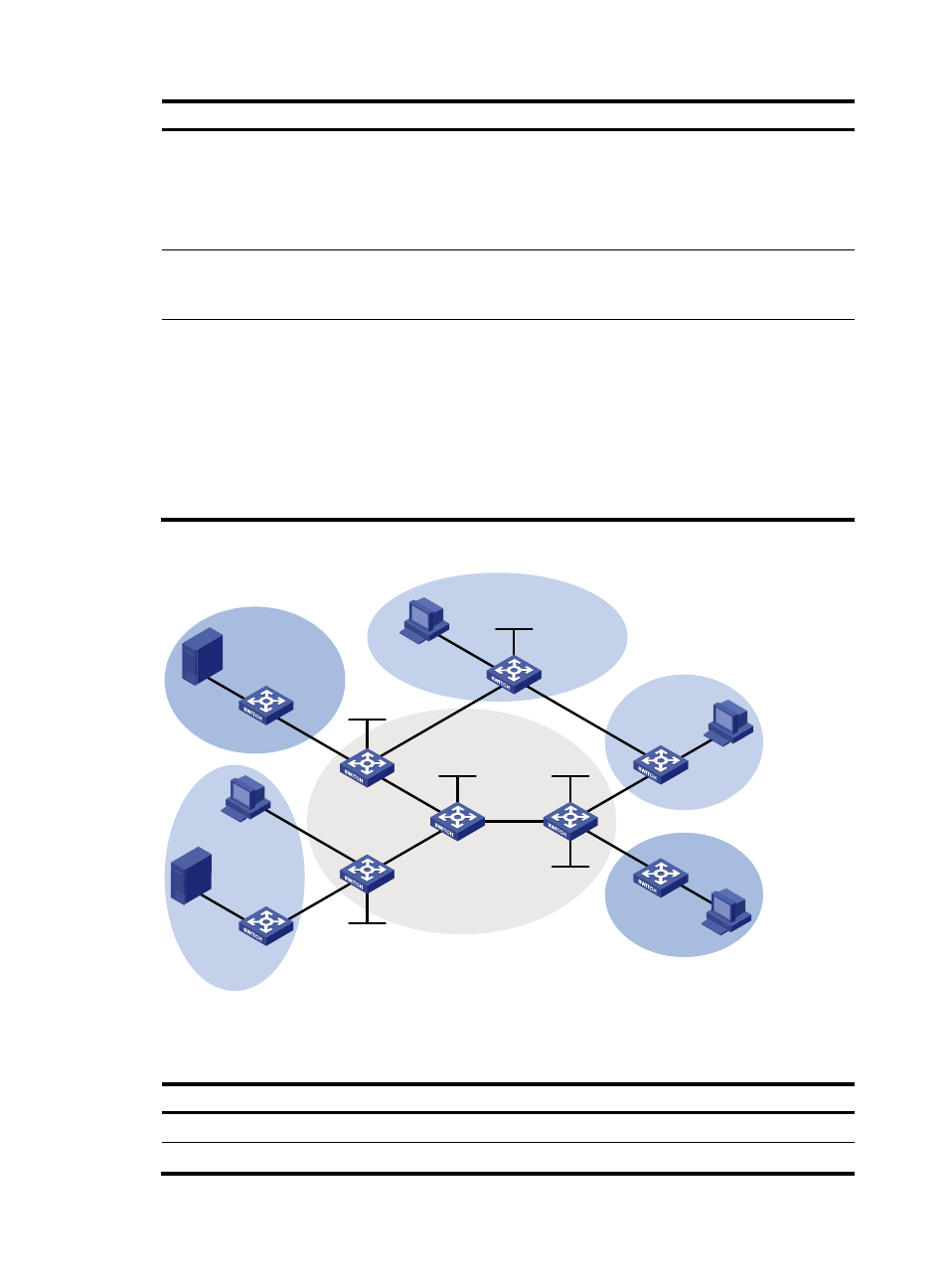
Figure 76 Network diagram
shows the interface and IP address assignment, and network topology scheme.
Table 19 Interface and IP address assignment
Device Interface
IP
address
Device
Interface
IP address
S 1
—
10.110.7.2/24
PE 3
Vlan-int19
192.168.8.1/24
S 2
—
10.110.8.2/24
PE 3
Vlan-int17
10.110.5.1/24
Loop1
Loop1
Loop1
Loop1
Loop2
Loop1
Vla
n-in
t12
S 2
S 1
P
PE 1
PE 2
PE 3
CE a1
CE a2
CE a3
CE b1
CE b2
Public
VPN b
VPN b
VPN a
VPN a
VPN a
R 1
R 2
R 3
R 4
Vlan-int10
Vlan-int30
Vlan
-int4
0
Vlan-int50
Vlan-int60
Vla
n-in
t11
Vla
n-in
t11
Vlan
-int2
0
Vla
n-in
t12
Vlan
-int1
3
Vlan
-int1
3
Vla
n-in
t14
Vla
n-in
t14
Vlan
-int1
5
Vlan
-int1
5
Vlan
-int1
6
Vlan
-int1
6
Vla
n-in
t17
Vla
n-in
t17
Vlan
-int1
8
Vlan
-int1
8
Vlan-int19
Vlan-int19