Configuration procedure – H3C Technologies H3C S12500 Series Switches User Manual
Page 119
103
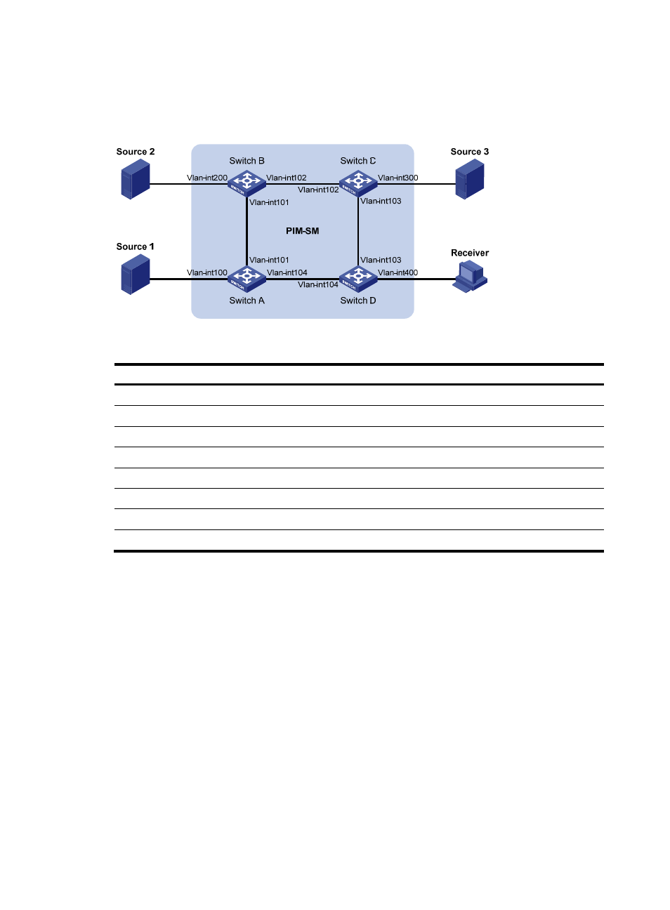
Source 1, Source 2, and Source 3 send multicast packets to multicast groups in the SSM group range. You
can configure the IGMP SSM mapping feature on Switch D so that the receiver host will receive multicast
data from Source 1 and Source 3 only.
Figure 35 Network diagram
Table 7 Interface and IP address assignment
Device
Interface
IP address
Device
Interface
IP address
Source 1 —
133.133.1.1/24 Source 3
—
133.133.3.1/24
Source 2 —
133.133.2.1/24 Receiver —
133.133.4.1/24
Switch A Vlan-int100
133.133.1.2/24 Switch C
Vlan-int300
133.133.3.2/24
Switch A Vlan-int101
192.168.1.1/24 Switch C
Vlan-int103
192.168.3.1/24
Switch A Vlan-int104
192.168.4.2/24 Switch C
Vlan-int102
192.168.2.2/24
Switch B Vlan-int200
133.133.2.2/24 Switch D
Vlan-int400
133.133.4.2/24
Switch B Vlan-int101
192.168.1.2/24 Switch D
Vlan-int103
192.168.3.2/24
Switch B Vlan-int102
192.168.2.1/24 Switch D
Vlan-int104
192.168.4.1/24
Configuration procedure
1.
Configure the IP address and subnet mask of each interface as shown in
shown.)
2.
Configure OSPF on the switches to make sure the network-layer is interoperable on the PIM-SM
domain and routing information among the switches can be dynamically updated. (Details not
shown.)
3.
Enable IP multicast routing, enable PIM-SM on each interface, and enable IGMP and IGMP SSM
mapping on the host-side interface:
# Enable IP multicast routing on Switch D, enable PIM-SM on each interface, and enable IGMPv3
and IGMP SSM mapping on VLAN-interface 400.
[SwitchD] multicast routing-enable
[SwitchD] interface vlan-interface 400
[SwitchD-Vlan-interface400] igmp enable
[SwitchD-Vlan-interface400] igmp version 3
[SwitchD-Vlan-interface400] igmp ssm-mapping enable