Comtech EF Data DM240XR User Manual
Page 76
DM240XR High-Speed Digital Modulator
Rear Panel Interfaces
MN-DM240XR– Revision 13
5–6
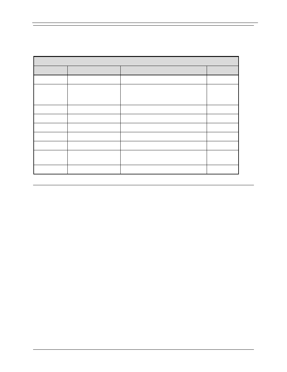
5.10 RF Redundancy Switch Control (J2)
The Each modulator has a 9-pin D-sub connector for the switch. A 1:1 cable is connected from
each modulator to the switch. The pinout for the control connector is listed in Table 5-5.
Table 5-5. RF Switch Control 9-pin ‘D’ Female (J2)
Pin No.
Signal
Description
Direction
5
Signal Ground
Modulator GND
Output
9
Backup Select
One modulator is designated as
Backup. This line is tied low on the
Backup Mod Control connector.
Input
1
+DC
+12V DC power
Output
2
nPrime_Sel
Forces On-Line output to Prime
Output
7
nBackup_Sel
Forces On-Line output to Backup
Output
8
Local Fault
Fault output of modulator
Output
4
Distant Fault
State of distant modulator
Input
3
Switch-State
Switch state monitor.
Logic '1' = Prime Online
Input
6
NC
---
---
5.11 Built in ASI/Advanced ASI Interface (J7)
The “Built In” ASI/AASI comes standard on every DM-240XR unit. This ASI interface is
supported on the BNC Connector. The interface complies with DVB ASI Electrical
Specifications. The maximum data rate is 216 Mbps.
The AASI Interface is a specialized mode of the normal ASI Interface. The interface allows the
user to input a variable rate data stream into the modulator (as long as the input data rate does not
exceed the programmed data rate). The AASI Interface inserts MPEG-2 Null Packets to provide
a constant data rate to the modulator.