Comtech EF Data DM240XR User Manual
Page 191
DM240XR High-Speed Digital Modulator
AutoEQ™ Interface Operation Guide
MN-DM240XR– Revision 13
D–11
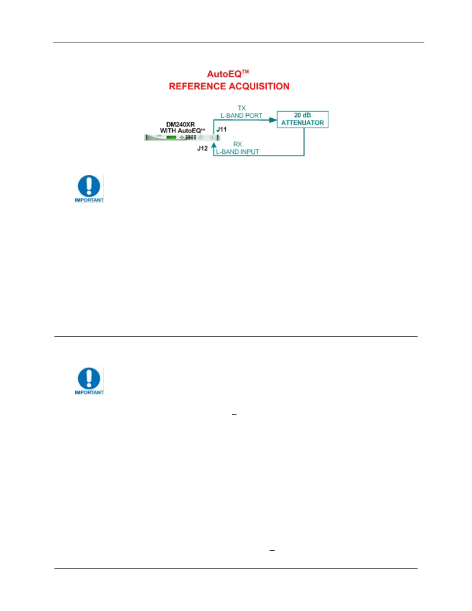
Figure 6. AutoEQ™ Ref Acq Set-up
For best results place the attenuator pad as close to the AutoEQ port (J12) as
possible.
9. Clear the events of the modulator by scrolling to CLEAR TO ERASE EVENTS> and press clear. Verify that the Event LED is now off. 10. Using the Front Panel menu, scroll to “EQ CALIBRATION” and set to “REF ACQ” a. After a successful calibration the event log will display “REF ACQ SUCCESSFUL” upon completion of this step. When the REF ACQ is complete, the “EQ CALIBRATION” will 11. Remove the interconnect cable installed in Step 8 above. 12. Verify through the event log that the system successfully calibrated the reference. D.9 Equalizer Calibration For best AutoEQ equalization calibration it is recommended that the amplifier be 1. Reprogram the DM240XR Modulator output frequency to the proper operating frequency of the Uplink system (if it was reprogrammed for Section 4.1 above) and the output power to the 2. Measure the center frequency of the down converted modulated signal. Using the front panel Menu, reprogram the AutoEQ™ to the center frequency of the down converted signal. The
revert to “NORMAL”.
run in its linear range and not saturated.
The AutoEQ™ RXRF Acquisition range is + 25 kHz from the programmed frequency and is not
programmable. To insure proper operation, the actual center frequency of the carrier should be
accurately measured with this measured value programmed into the AutoEQ™. This can be
accomplished by generation a CW (Carrier Wave) frequency with the modulator, and measuring
the downlink L-Band frequency with an accurate frequency counter or spectrum analyzer.
system operating level. Connect the DM240XR Modulator output to the Uplink system.
Enable the modulator and adjust all uplink parameters as required for proper uplink
operation.
AutoEQ™ programmed frequency must be within + 25 kHz of the measured frequency in