Comtech EF Data DM240XR User Manual
Page 74
DM240XR High-Speed Digital Modulator
Rear Panel Interfaces
MN-DM240XR– Revision 13
5–4
5.5
External Reference (Input)
The External Reference Input (J8) is supplied to allow the customer to phase-lock the modulator’s
internal oscillator to an external reference.
This female BNC Connector accepts a 1.5 – 5 Vp-p @ 50 Ohms. The frequency range of the
external reference is 1 – 10 MHz in 8 kHz steps.
5.6
Remote Port (I/O)
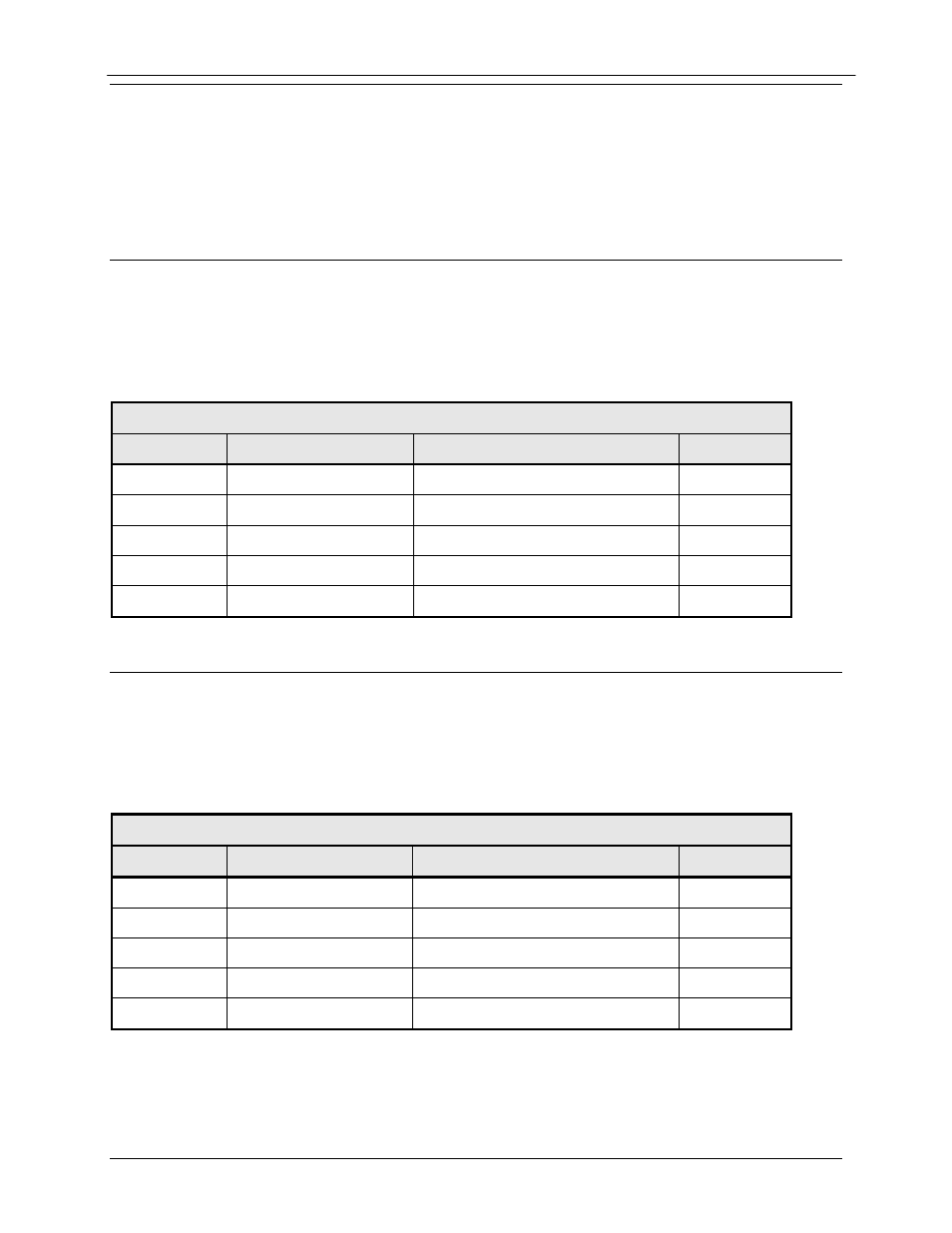
The Remote Port Interface (J4) can be used for the monitor & control functions of the unit. The
physical interface is a female 9-Pin D-Sub Connector. This bi-directional port complies with
RS-485 Electrical Specifications. Refer to Section 7.6 for protocol and programming details.
Pinouts are listed in Table 5-1.
Table 5-1. J4 - RS-485 Remote Control- 9-Pin ‘D’ Female
Pin No.
Signal
Description
Direction
1
Tx (B)
Transmit Data (+)
Output
5
GND
Ground
---
6
Tx (A)
Transmit Data (-)
Output
8
Rx (B)
Receive Data (+)
Input
9
Rx (A)
Receive Data (-)
Input
5.7
Terminal Port (I/O)
The Terminal Port Interface (J1) can be used for the monitor & control functions of the unit. The
physical interface is a female 9-Pin D-Sub Connector. This bi-directional port complies with
RS-232 Electrical Specifications. Refer to Section 4.8 for terminal interface details. The pinouts
are listed in Table 5-2.
Table 5-2. J1 - RS-232 Terminal Port - 9-Pin ‘D’ Female
Pin No.
Signal Name
Description
Direction
3
TxD
Transmit Data
Output
2
RxD
Receive Data
Input
5
GND
Ground
---
7
RTS
Request to Send
Output
8
CTS
Clear to Send
Input