Comtech EF Data DM240XR User Manual
Page 141

DM240XR High-Speed Digital Modulator
Web Browser
MN-DM240XR– Revision 13
10–3
Table 10-1.
Item Number
Description
Function
1
Product Name
This describes what product is that the
interface is connected to.
2
Product Name/Location
This can be used by the user to identify the
unit.
3
Alarm and Monitor
Displays fault status and performance
monitoring of unit.
4
Gel-Tab Area
This area allows access to data and control
input of unit. Moving the cursor across the
Gel-Tabs drop down menus appear and
allow editing of the data entry area.
5
Data Entry Area
Parameter editing is done in this area.
6
Product Information
Contact Information
Access to technical trouble-shooting,
product options and specifications is
accomplished by selecting one and clicking
on that function. Contacting Radyne via
Email is possible by clicking on “Contact
Us”.
10.2.1 LED Indicators
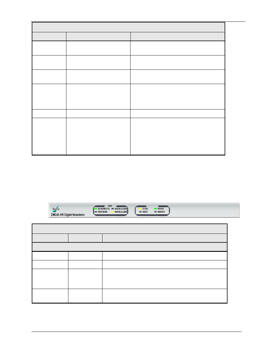
Twelve LEDs on the GUI Interface (Refer to Table 10-2) indicate the status of the modems
operation. The LED colors maintain a consistent meaning. Green is appropriate for normal
operation, Yellow means that there is a condition not proper for normal operation, and Red
indicates a fault condition that will result in lost communications.
Table 10-2.
LED
Color
Function
Modem LED Indicators
Power
Green
Indicates that the unit is turned on.
Fault
Red
Indicates a hardware fault for the unit.
Event
Yellow
Indicates that a condition or event has occurred that the
modem has stored in memory. The events may be viewed
from the GUI or in the Terminal Mode.
Remote
Green
Indicates that the unit is in the process of updating firmware
with FTP.
