Comtech EF Data DM240XR User Manual
Page 24
DM240XR High-Speed Digital Modulator
User Interfaces
MN-DM240XR– Revision 13
4–2
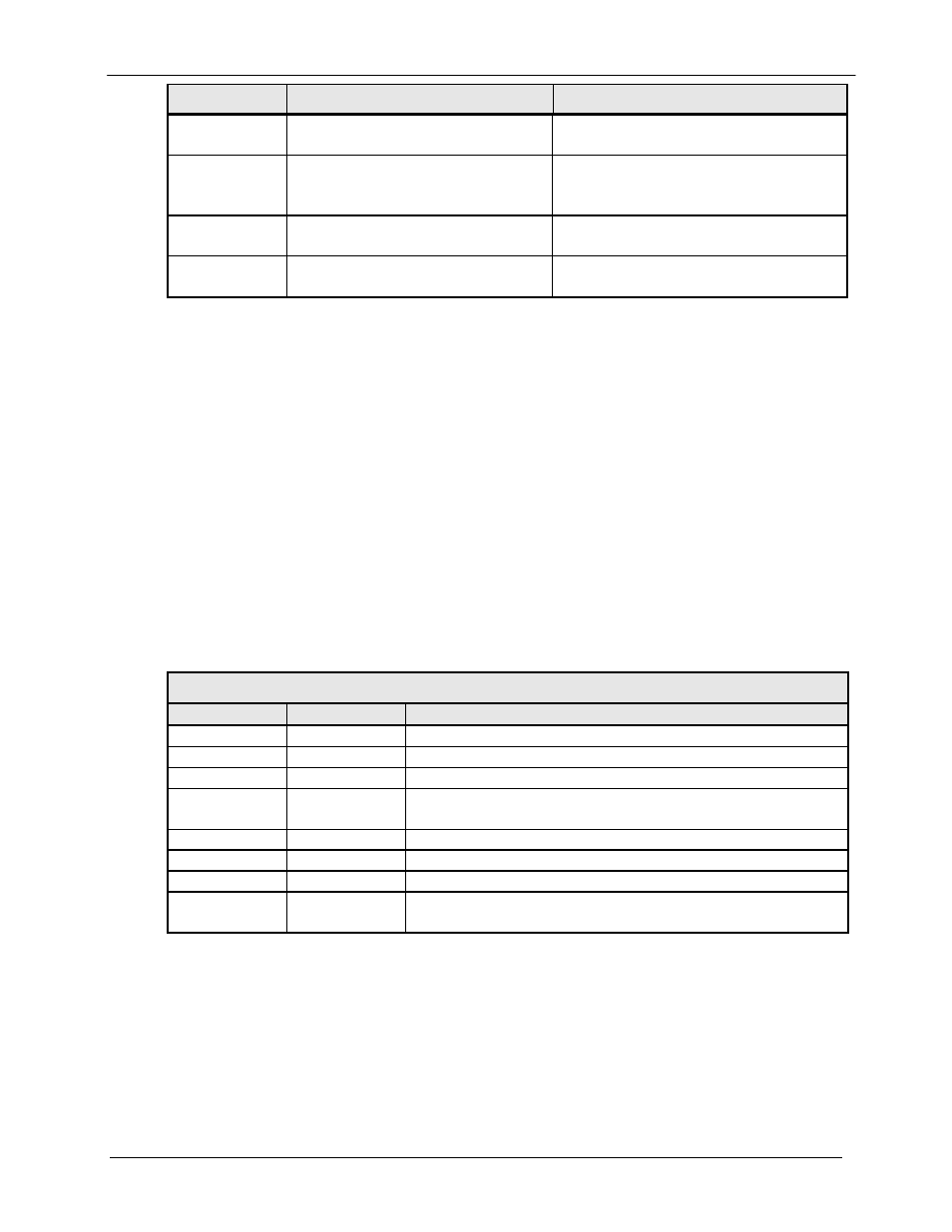
Item Number
Description
Function
1
LCD Front Panel Display
Displays DM240XR Operating
parameters and Configuration data.
2
Cursor Control Arrows
Controls the up, down, right and left
motion of the cursor in the LCD
Display window (see Figure x-x).
3
Numeric Keypad
Allows entry of numeric data and Clear
and Enter function keys.
4
Operational Function LEDs
See Table 4-2 for a description of these
LED Indicators.
4.2.1 Front Panel LCD Display
The front panel display is a 2 line by 16-character LCD display. The display is lighted and the
brightness can be set to increase when the front panel is currently in use. The LCD display
automatically dims after a period of inactivity. The display has two distinct areas showing
current information. The upper area shows the current parameter being monitored, such as
‘Frequency’ or ‘Data Rate’. The lower line shows the current value of that parameter. The LCD
display is a single entry window into the large matrix of parameters that can be monitored and set
from the front panel.
4.2.2 Front Panel LED Indicators
Eight LEDs on the DM240 front panel (Refer to Table 4-2) indicate the status of the DM240’s
operation. The LED colors maintain a consistent meaning. Green signifies that the indication is
appropriate for normal operation, Yellow means that there is a condition not proper for normal
operation, and Red indicates a fault condition that will result in lost communications.
Table 4-2.
LED
Color
Function
Transmit On
Green
Indicates the DM240 XRTransmitter is turned on.
Major Alarm
Red
Indicates that the transmit direction has failed, losing traffic.
Minor Alarm
Yellow
Indicates a transmit warning condition exists.
Test Mode
Yellow
Indicates the modulator is involved in a current test mode
activity.
Power
Green
Indicates the DM240XR unit is currently powered up.
Fault
Red
Indicates a common fault exists such as power out of spec.
Event
Yellow
Indicates that events have been logged into the event buffer.
Remote
Green
Indicates that the unit is set to respond to the remote control
or terminal input.
4.2.3 Front Panel Keypad
The front panel keypad consists of two areas: a 10-key numeric entry with 2 additional keys for
the ‘Enter’ and ‘Clear’ function. The second area is a set of ‘Arrow’ or ‘Cursor’ keys (
↑), (↓),
(
→), (←), used to navigate the parameter currently being monitored or controlled. Table 4-3
describes the key functions available at the front panel.