Comtech EF Data DM240XR User Manual
Page 75
DM240XR High-Speed Digital Modulator
Rear Panel Interfaces
MN-DM240XR– Revision 13
5–5
5.8
Alarm Port
The Alarm Connector (J3) is used to indicate the fault condition of the modulator to external
equipment. This male 9-Pin D-Sub Connector provides connection to two Form-C relays and an
open collector output. The user can distinguish between major and minor alarms with the relays.
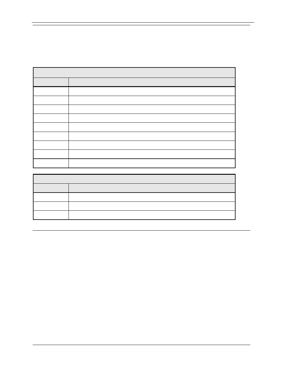
Refer to Table 5-3 for connector pinouts. Table 5-4 below describes the alarm indications.
Table 5-3. Alarm Connector J3 Pin Assignment
Pin No.
Connection
1
Relay 1 NO
2
Relay 1 C
3
Relay 1 NC (Major Alarm)
4
Ground
5
No Connect
6
Mod Fault (Open Collector)
7
Relay 2 NO
8
Relay 2 C
9
Relay 2 NC (Minor Alarm)
Table 5-4. Alarm Indications
Alarm
Pin Description
None
1 – 2 shorted, 7 – 8 shorted, open collector output driven low
Minor
1 – 2 shorted, 8 – 9 shorted, open collector output driven low
Major
2 – 3 shorted, 7 – 8 shorted, open collector output open
5.9
IF Output Port (J10 & J11)
The DM240XR is designed to support IF and L-band frequencies. The rear panel of the
DM240XR has separate IF and L-Band connectors. Refer to figure 5.1a. The IF frequency is
programmable from 50-90Mhz to 100-180Mhz. The IF port is a 75 ohm BNC connector (J10).
The output power level is programmable from –25 to 0dBm in 0.1 dBm steps. The L-Band
frequency is programmable from 950 to 2050Mhz. The L-band port is a 50 Ohm SMA female
connector (J11). The output power level is programmable from -25 to 0 dBm in 0.1 dBm steps.
5.9.1 Output Monitor Port (J9)
The output monitor port on the DM240XR is an 50 Ohm SMA female connector. The monitor is
a sample of the output frequency that is –20dBc +/-5dB from the output frequency power level.