1 if connector group, Rx’ if connector, 2 ‘tx’ if connector – Comtech EF Data ODM-840 User Manual
Page 46: 1 ‘rx’ if connector
ODM/R-840 Outdoor Remote Router
Revision 0
ODM/R Connections
MN-ODM840
2–6
Table 2-1. ODM-840 Rear Panel Connectors
Connector Group Name
Connector Type
Function
IF Group
Sect. 2.2.1
Rx 50Ω Type ‘N’ female
L-Band Input
Tx 50Ω Type ‘N’ female
L-Band Output
Terrestrial Data
Group
Sect. 2.2.2
ETHERNET T/M
(Traffic/Management)
RJ-45 female
10/100/1000 BaseT Gigabit Ethernet interface
(IEEE 802.3ab) and Ethernet management/data
interface (IEEE 802.3u)
G.703
(ODM-840 only)
IN
BNC-F
G.703 E1 Input
OUT BNC-F
G.703 E1 Output
Utility Group
Sect. 2.2.3
CONSOLE/REDUNDANCY
19-pin Circular
Connector
Serial Remote Interface (EIA-232)
Note: 1:1 Redundancy is a functional offering for
the ODM-840 only.
The European EMC Directive (EN55022, EN50082‐1) requires using properly shielded cables
for DATA I/O. These cables must be double‐shielded from end‐to‐end, ensuring a continuous
ground shield.
See Sect. 3.1 Cabling Connections Types for information about each connector type and
its connection instructions.
2.2.1 IF Connector Group
THERE MAY BE DC VOLTAGES PRESENT ON THE ODM‐840 TYPE ‘N’ RX AND TX IF
CONNECTORS, UP TO A MAXIMUM OF 48 VOLTS; FOR THE ODMR‐840 TYPE ‘N’ RX
CONNECTORS, UP TO A MAXIMUM OF 25 VOLTS.
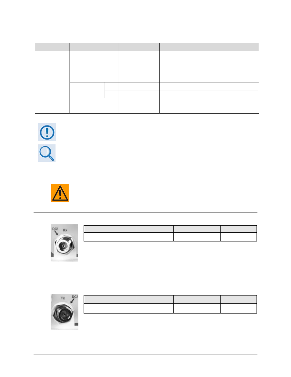
2.2.1.1 ‘Rx’ IF Connector
Connector Type
Name
Description
Direction
Type ‘N’ 50Ω Female
Rx
Rx IF Signal, L-Band
In
2.2.1.2 ‘Tx’ IF Connector
Connector Type
Name
Description
Direction
Type ‘N’ 50Ω Female
Tx
Tx IF signal, L‐ Band
Out