Bestlogic ™plus composition – Basler Electric DGC-2020ES User Manual
Page 124
116
9469200990 Rev C
BESTlogic
™Plus Composition
There are three main groups of objects used for programming BESTlogicPlus. These groups are I/O,
Components, and Elements. For details on how these objects are used to program BESTlogicPlus, see
the paragraphs on Programming BESTlogicPlus, later in this chapter.
I/O
This group contains Input Objects, Output Objects, Alarms, Pre-Alarms, Senders, and Logic Control
Relays. Table 23 lists the names and descriptions of the objects in the I/O group.
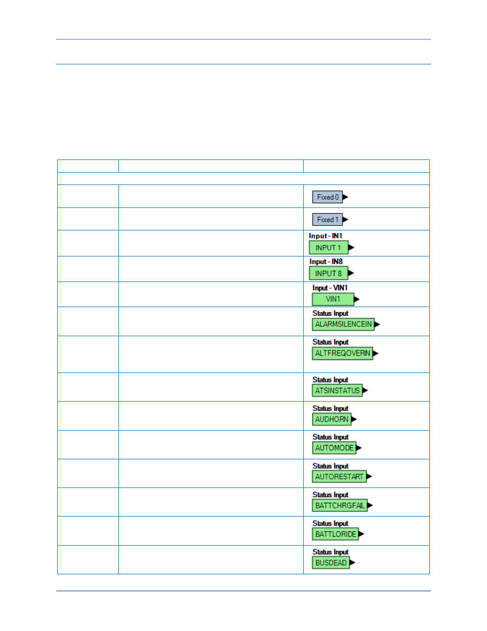
Table 23. I/O Group, Names and Descriptions
Name
Description
Symbol
Input Objects
Logic 0
Always false (Low).
Logic 1
Always true (High).
Physical Inputs
IN1 – IN7
True when Physical Input x is active.
Remote Inputs
IN8 – IN17
True when Remote Input x is active. (Available when
an optional CEM-2020 is connected.)
Virtual Inputs
VIN1 – VIN4
True when Virtual Input x is active.
Status Input
Alarm Silence
True when the Alarm Silence logic element is true or
the Alarm Silence button is pressed on the front panel.
Status Input
Alternate
Frequency
Override
True when the Alternate Frequency Override logic
element is true.
Status Input
ATS Input
True when the ATS (Auto Transfer Switch) input is true
or the ATS logic element is true.
Status Input
Audible Horn
True when the Audible Horn is active.
Status Input
Auto Mode
True when the DGC-2020ES is in Auto Mode or the
Auto Mode logic element is true.
Status Input
Auto Restart
True when the Automatic Restart function is active.
Status Input
Battery Charger
Fail
True when the Battery Charger Fail input is true.
Status Input
Battle Override
True when the Battle Override input is true.
Status Input
Bus Dead
True when the Bus Dead condition settings have been
exceeded.
BESTlogic
™Plus
DGC-2020ES