Ethernet setup procedure – AMETEK SFA Series Ethernet Programming User Manual
Page 43
SG Series Programming
Ethernet Configuration and Remote Programming
M550129-03 Rev K
5-3
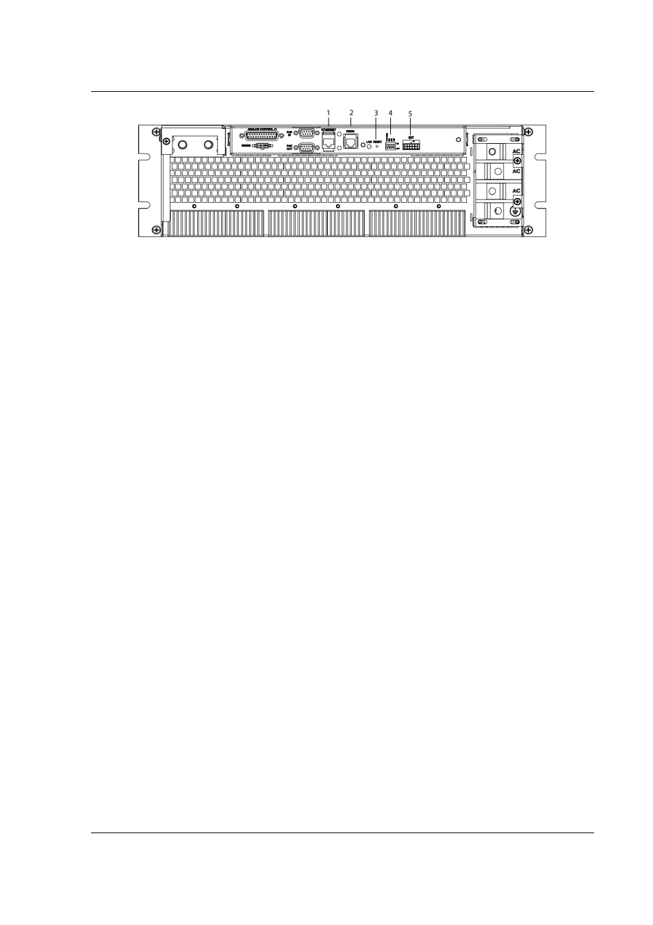
Figure 5-3. SGI Rear Panel with Ethernet/RS232 Options (4-pin Config Switch shown)
1 – Ethernet (RJ-45) connector. Adjacent to the RJ-45 connector are two green LEDs.
If one of the LEDs is lit, the link is connected either to a hub switch or to another
host. If both are lit, the connection speed is 100MB.
2 – RS232 (RJ-type 6P6C) connector.
3 – Reset switch and green dual-purpose NET LED.
Reset switch (must be depressed until NET LED begins blinking, which could take
five or more seconds) returns configuration parameters to factory default settings
(see Section 4.3.2).
NET LED: when solid-lit, indicates Network Connectivity; blinking indicates
Instrument ID (See “Instrument ID” in Settings, Section 5.5.3). If the LED is off,
there is no Ethernet connection found by the power supply.
4 – Configuration Switch (may be 8-pin or 4-pin). For correct settings see Section
5.2.5)
5 –External User Control Signal Connector (see Section 5.3)
5.2
ETHERNET SETUP PROCEDURE
The Ethernet option is installed into the supply at the factory. Use the Setup
Procedure that applies to your system and application to configure the
Ethernet.
There are four methods of setting the IP address of the unit, each of which is
described in the subsections that follow:
•
Set an IP address through DHCP (Primary default).
•
If DHCP is not available, the unit can assign itself an IP address in the
Auto-IP (dynamic link local addressing) range (Secondary default).
•
Use the serial communications port to manually assign an IP address.
(IP address can be set via the front panel on SGI units.)
•
Set the IP address through the Web page interface.