AMETEK SFA Series Ethernet Programming User Manual
Page 42
Ethernet Configuration and Remote Programming
SG Series Programming
5-2
M550129-03 Rev K
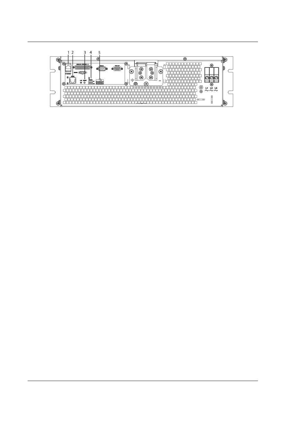
Figure 5-2. SG Rear Panel with Ethernet/RS232 Options
1 – Ethernet (RJ-45) connector. Adjacent to the RJ-45 connector are two green LEDs.
If one of the LEDs is lit, the link is connected either to a hub switch or to another
host. If both are lit, the connection speed is 100MB.
2 – RS232 (RJ-type 6P6C) connector.
3 – Reset switch and green dual-purpose NET LED.
Reset switch (must be depressed until NET LED begins blinking, which could take
five or more seconds) returns configuration parameters to factory default settings
(see Section 4.3.2).
NET LED: when solid-lit, indicates Network Connectivity; blinking indicates
Instrument ID (See “Instrument ID” in Settings, Section 5.5.3). If the LED is off,
there is no Ethernet connection found by the power supply.
4 – Configuration Switch (may be 8-pin or 4-pin). For correct settings see Section
5.2.5)
5 –External User Control Signal Connector (see Section 5.3)
- CW-M (48 pages)
- CW-M Corrected Table 4-2 in (1 page)
- CW-P (62 pages)
- Lx Series (205 pages)
- CW Series Programming Manual (25 pages)
- Ls Series II Programming Manual (242 pages)
- Compact i/iX Series (157 pages)
- Compact IX 2253 (157 pages)
- Compact i/iX Series Software Manual (203 pages)
- ASD Series Quick Start (5 pages)
- ASD Series (120 pages)
- i-iX Series II Programming Manual (226 pages)
- DLM 600W Series Programming Manual (24 pages)
- M131 Programming Manual (99 pages)
- DLM Series (74 pages)
- DLM 600W Series (82 pages)
- BPS Series (153 pages)
- DLM600 Series (16 pages)
- DCS-E 1.2kW Series (65 pages)
- DLM-E 4kW Series Programming Manual (32 pages)
- M136 (8 pages)
- DCS-E 3kW Series (94 pages)
- CTS 3.0 (166 pages)
- CSW Series (174 pages)
- 2003RP (126 pages)
- 2001RP (131 pages)
- MX CTSH (151 pages)
- MXCTSL Administrator Manual (27 pages)
- MX CTSL (157 pages)
- RS Series (228 pages)
- MX Series Installation Manual (35 pages)
- Ls AC source (2 pages)
- MX15 Series (184 pages)
- Ls Series II (226 pages)
- Lx Series Driver Manual (275 pages)
- MX Series Rev: AY (257 pages)
- iX Series (341 pages)
- i-iX Series II (258 pages)
- GUPS 2400A-108 (36 pages)
- HPD Series (58 pages)
- HPD Series Operation Manual (41 pages)
- HPD Series GPIB-Multichannel (134 pages)
- PLA-PLW Programming Manual (74 pages)
- ReFlex Mating Connnectors for Controller (3 pages)
- LPDC-16V (4 pages)