Adjustment for voltage mode – AMETEK SFA Series Ethernet Programming User Manual
Page 149

SG Series Programming
Calibration
M550129-03 Rev K
7-15
7. Verify the unit is set to 100% ± 0.8% of full-scale output current. If necessary,
adjust R33 (on the isolated interface adapter) for 100% of full-scale current on
the shunt.
8. Set the programming source for 0.5V ± 1mV.
9. Verify that the unit is set to 10% ± 0.8% of full-scale output current. If necessary,
adjust R47 (on the isolated interface adapter) for 10% of full-scale current on
the shunt.
10. Repeat the steps above as required to obtain the required accuracy.
7.8.2
Adjustment for Voltage Mode
STEP
DESCRIPTION
1. Disable AC power to the unit. Remove the current shunt from the output and
verify that there is no load attached.
2. Remove the precision meter leads from the current shunt and apply them
across the output terminals.
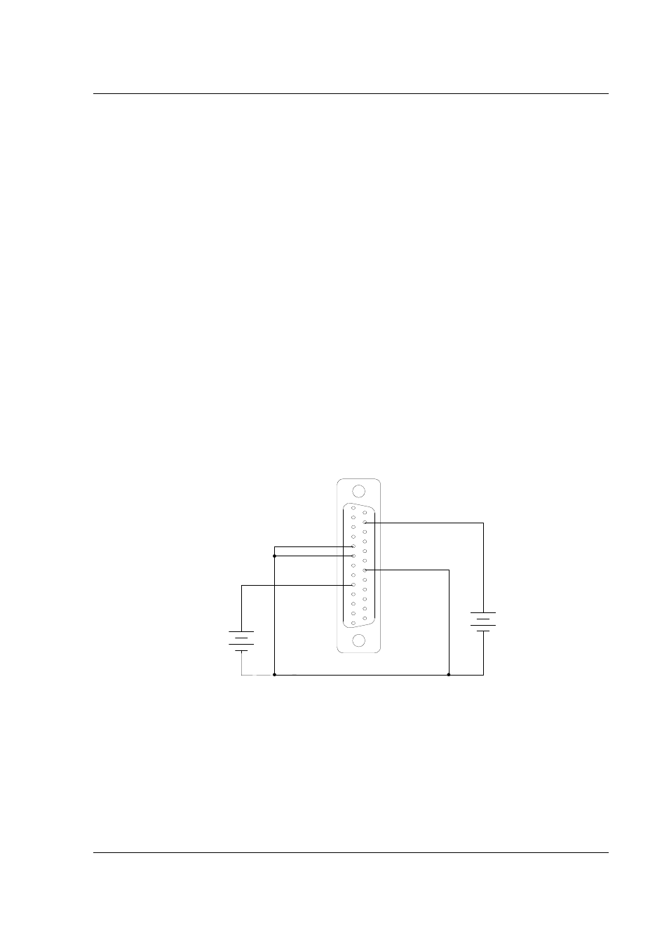
3. Set the SGI series unit to operate in remote voltage programming mode using
an external 0-5 VDC voltage source as shown in Figure 7-5.
+
-
1
13
20 VP RTN
COM 6
+
-
15 VP 10V
VP 5V 9
0-5 VDC
VOLTAGE
SOURCE
0-10 VDC
VOLTAGE
SOURCE
Figure 7-5. Remote Voltage Programming Using 0-5 VDC or 0-10 VDC Voltage Source
4. Apply AC power and press "Output On" switch (Figure 7-4).
5. Set the programming source to 5.0V ±1mV.
6. Verify that the unit is set to 100% ± 0.25% of full-scale output voltage. If
necessary adjust R39 (on the isolated interface adapter) for 100% output
voltage.
