AMETEK MX15 Series User Manual
Page 78
User Manual
– Rev M
California Instruments
MX15
78
4.2.5
CONTROL Menus
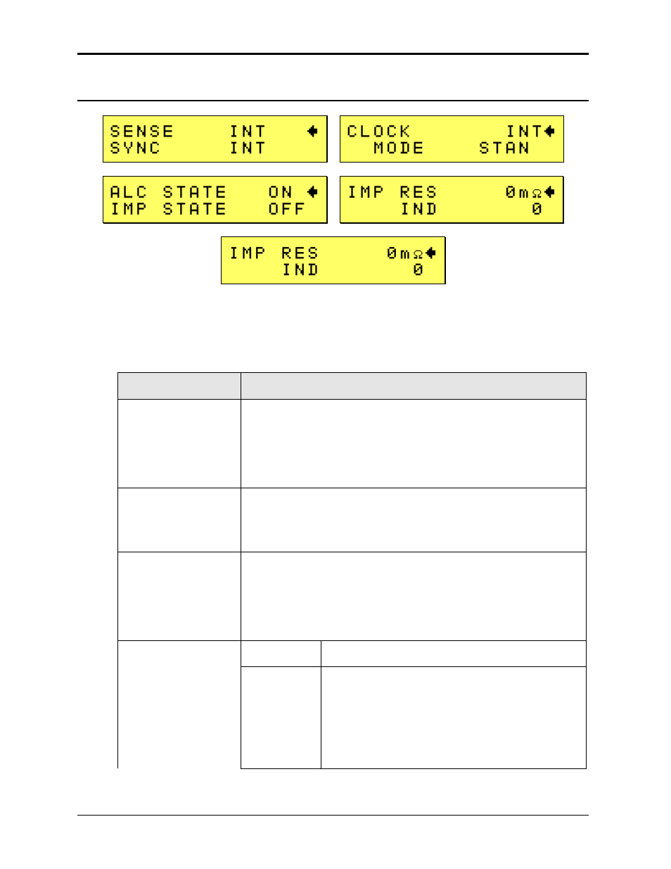
Figure 4-5: CONTROL Menus
The CONTROL menu is shown in Figure 4-5 and can be reached by selecting the Menu key,
selecting the CONTROL entry using the DOWN cursor key and then pressing the Enter key.
The CONTROL menu is used to change secondary output parameters. The following choices are
available in the CONTROL menus:
ENTRY
DESCRIPTION
SENSE
Selects internal or external (remote) voltage sense mode. If INT is
selected, the voltage is sensed at the output terminal block. If EXT is
selected, the voltage is sensed at the external sense connector. If
external sense is selected, care must be taken to connect the
external sense lines at the load. For sense leads longer than 1
meter, twisted pairs should be used.
SYNC
Selects the external sync mode if available. Default is internal sync,
which means a free running time base. The time base can be
synchronized to an external sync signal by selecting external sync
mode.
CLOCK
Selects internal or external clock source. The MX Series controller
uses an open-air crystal time base with an accuracy of 100 ppm. The
external clock mode is used to support the
–LKS option. For use as
an auxiliary unit in a clock and lock system, this field must be set to
EXT. A unit with
–LKS option can be used stand-alone if needed by
setting the INT clock mode.
INT
Default, internal clock.
EXT
Auxiliary unit (-LKS) driven by master (-LKM) clock
input.
Note: When selecting EXT mode, make sure the
Clock and Lock BNC cables are connected to the
Master (-LKM) unit. If not, there will be no output on
the
–LKS unit. See section 3.10 for connection
information.