AMETEK MX15 Series User Manual
Page 12
User Manual
– Rev M
California Instruments
MX15
12
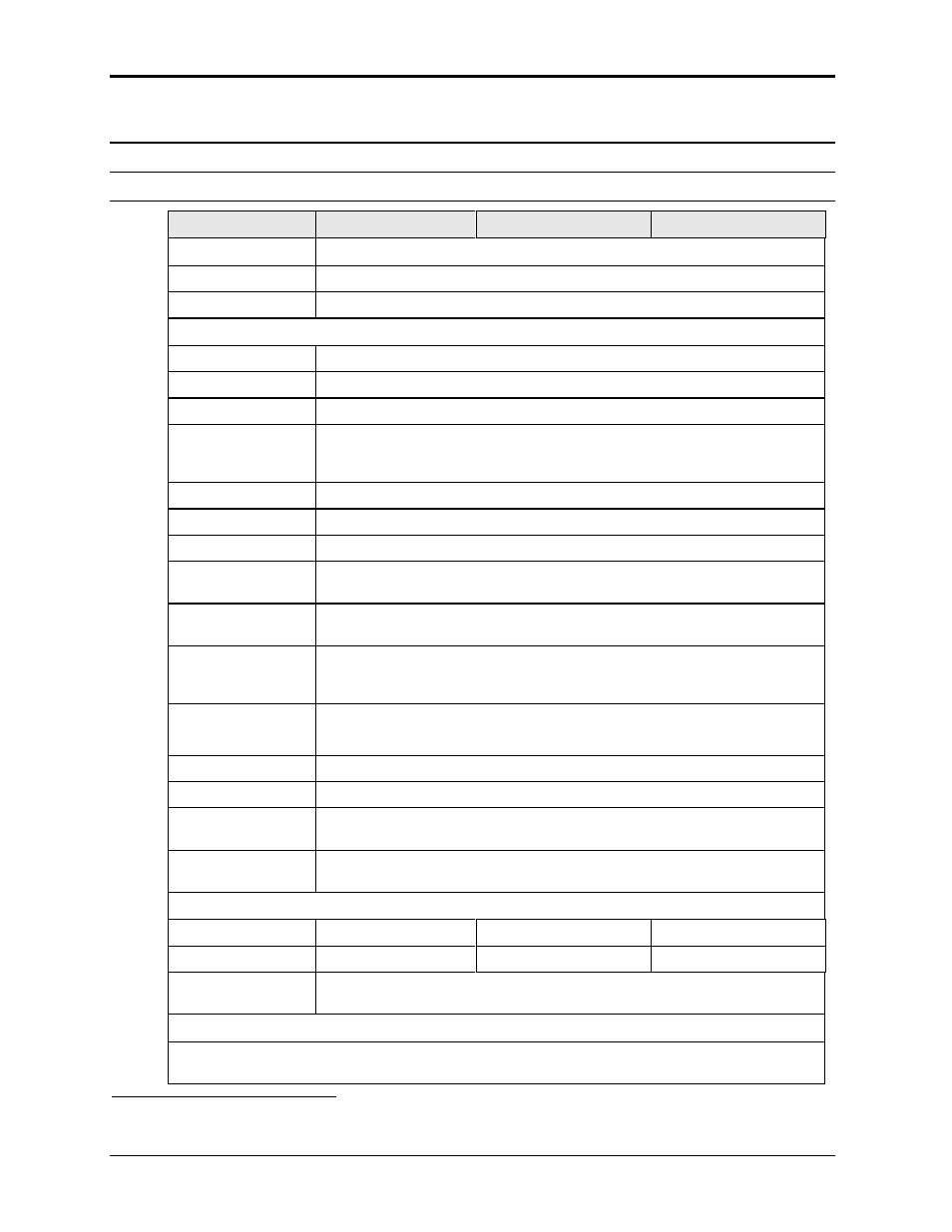
2.1.2
Output
Note: All specifications are for AC and DC unless otherwise indicated.
Output Parameter
MX15
MX30/2
MX45/3
Modes
Std Controller
AC, DC
Pi Controller
AC, DC, AC+DC
Voltage:
Ranges (L-N):
AC Mode
Low: 0 - 150 V / High: 0 - 300 V
DC Mode
Low: 0 - 200 V / High: 0 - 400 V
AC+DC Mode
AC: Low: 0 - 150 V / High: 0 - 300 V
DC Offset: Low Vrange: 0 - 150 V
High Vrange: 0 - 220 V
Resolution:
AC Mode
0.1 V
DC Mode
0.1 V
AC+DC Mode
AC:
0.1 V
DC Offset:
0.01 V
Accuracy:
± 0.3 V AC mode
± 1 V DC mode
Distortion THD
1
:
(Resistive load)
< 1 % @ 16 - 66 Hz
< 2 % @ 66 - 500 Hz
< 3 % @ > 500 Hz
Load Regulation:
0.25 % FS @ DC - 100 Hz
0.5 % FS @ > 100 Hz
Line Regulation:
0.1% for 10% input line change
DC Offset Voltage:
< 20 mV
Output Noise:
(20 kHz to 1 MHz)
< 2 V
RMS
low V Range
< 3 V
RMS
high V Range
Output Coupling
DC coupled
Except on optional -HV or -XV Voltage range output, which is AC coupled.
Power (total power for all phases, either range, at full scale voltage)
AC Mode
15 KVA
30 KVA
45 KVA
DC Mode
10 KW
20 KW
30 KW
AC+DC Mode
The maximum power and current in the AC+DC mode is equal to that in the
DC mode
Current
Note: Current, maximum amps indicated per phase available between 50 and 100 % of voltage
range.
1
The distortion specification for the MX Series is valid for resistive load conditions.