AMETEK MX15 Series User Manual
Page 51
User Manual
– Rev M
California Instruments
MX15
51
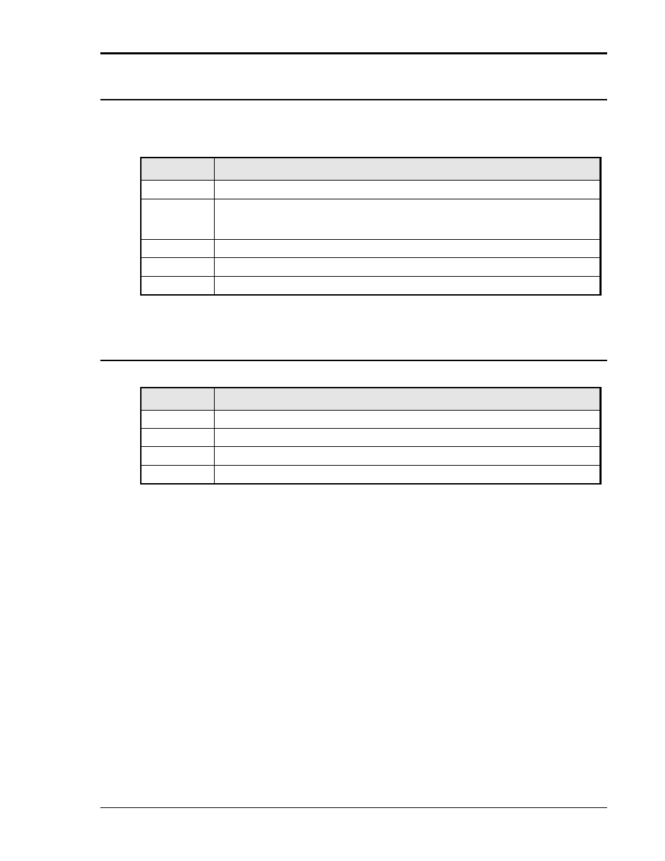
3.7.3
BNC Connectors
BNC connectors. Functions are called out on rear panel decal. Table shows connections from
left to right when standing at the rear of the MX15 cabinet.
BNC
Description
1
Trigger Input (TTL input)
2
Trigger Output (TTL output) (Same signal connection as Function Strobe. Some units
may not have this output connected. If you don’t get an output trigger on this BNC, use
the Function Strobe BNC instead.)
3
Function Strobe (TTL output) (Same signal connection as Trigger Output)
4
Clock (TTL output on Master / TTL input on Auxiliary)
5
Lock (TTL output on Master / TTL input on Auxiliary)
Table 3-5: BNC Connectors
3.7.4
External Sense Connector
Pin
Description
1
Phase A sense
2
N/C
3
N/C
4
Neutral sense
Table 3-6: External Sense Connector
- CW-M (48 pages)
- CW-M Corrected Table 4-2 in (1 page)
- CW-P (62 pages)
- Lx Series (205 pages)
- CW Series Programming Manual (25 pages)
- Ls Series II Programming Manual (242 pages)
- Compact i/iX Series (157 pages)
- Compact IX 2253 (157 pages)
- Compact i/iX Series Software Manual (203 pages)
- ASD Series Quick Start (5 pages)
- ASD Series (120 pages)
- i-iX Series II Programming Manual (226 pages)
- DLM 600W Series Programming Manual (24 pages)
- M131 Programming Manual (99 pages)
- DLM Series (74 pages)
- DLM 600W Series (82 pages)
- BPS Series (153 pages)
- DLM600 Series (16 pages)
- DCS-E 1.2kW Series (65 pages)
- DLM-E 4kW Series Programming Manual (32 pages)
- M136 (8 pages)
- DCS-E 3kW Series (94 pages)
- CTS 3.0 (166 pages)
- CSW Series (174 pages)
- 2003RP (126 pages)
- 2001RP (131 pages)
- MX CTSH (151 pages)
- MXCTSL Administrator Manual (27 pages)
- MX CTSL (157 pages)
- RS Series (228 pages)
- MX Series Installation Manual (35 pages)
- Ls AC source (2 pages)
- Ls Series II (226 pages)
- Lx Series Driver Manual (275 pages)
- MX Series Rev: AY (257 pages)
- iX Series (341 pages)
- i-iX Series II (258 pages)
- GUPS 2400A-108 (36 pages)
- HPD Series (58 pages)
- HPD Series Operation Manual (41 pages)
- HPD Series GPIB-Multichannel (134 pages)
- PLA-PLW Programming Manual (74 pages)
- ReFlex Mating Connnectors for Controller (3 pages)
- LPDC-16V (4 pages)