Principle of operation, General, Overall description – AMETEK MX15 Series User Manual
Page 111: 5 principle of operation
User Manual
– Rev M
California Instruments
MX15
111
5 Principle of Operation
5.1 General
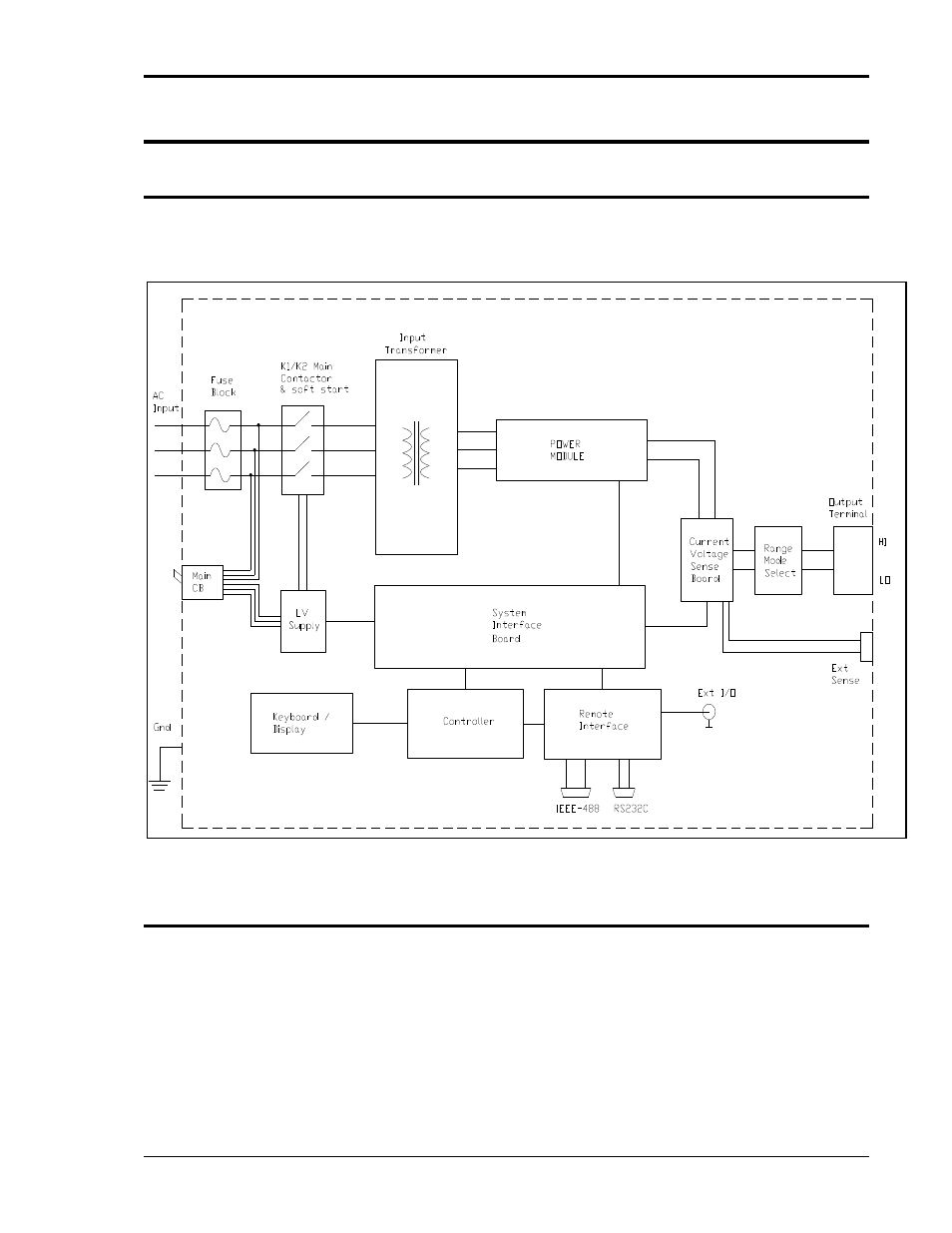
An explanation of the circuits in the MX15 Series is given in this section. Refer to Figure 5-1 for
a basic functional block diagram of the system. Figure 5-2 shows a more detailed system
interconnect for a MX15-1 single-phase output unit.
Figure 5-1: MX Series Functional Block Diagram
5.2 Overall Description
Three-phase input power is routed to the back of the cabinet to a fuse holder terminal block. The
rear access panel has to be removed to gain access to the AC input connection fuse block. From
the fuse block, the AC input is connected to the three-phase input transformer primary. The input
transformer provides the required isolation between input and output of the MX and
accommodates various input voltage ranges by employing multiple taps. Three sets of single-
phase output secondaries are provided by the transformer to produce three 140 VAC
unregulated output AC buses. Each of these outputs is fed into the power module. The power
module is located in the middle of the MX chassis and can be pulled out from the front after
removing the front access panel and disconnecting the power input and output wiring.