Multiple cabinet system configurations (incl – AMETEK MX15 Series User Manual
Page 56
User Manual
– Rev M
California Instruments
MX15
56
3.8 Multiple Cabinet System Configurations (incl.
–MB)
Multi-cabinet MX models consist of two or three autonomous or Auxiliary MX15-1Pi units.
Auxiliary units do not have their own controller and are identified easily by their blank front panel.
Master units each have their own controller but can be configured as auxiliary units by
disconnecting the ribbon cable marked J17 between the controller and the system interface
board (P/N 7005-701-1). This disables the controller and allows the MX15 to operate as an
Auxiliary unit. (Requires removal of the top cover)
When used as a multi-cabinet system for higher power applications, the controllers in the unit(s)
acting as the auxiliary to the master are either disabled or not present.
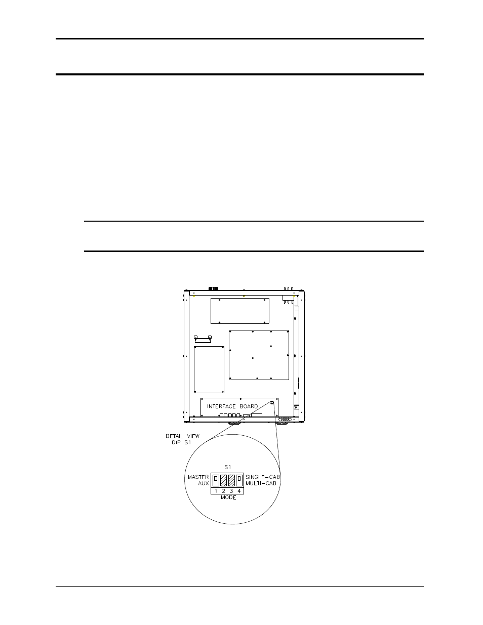
In addition to disabling the controller if present (as described above), the DIP switch (S1), located
on the GPIB / RS232C / IO assembly in the auxiliary cabinets, settings need to be changed.
(Requires removal of the top cover). The correct switch settings are shown below. (shown set for
Master cabinet). Note that all units must be powered down before reconfiguring. Also, the output
wiring must be changed to accommodate the new configuration.
Note: If the units being re-configured for multi-cabinet operation were not factory
configured this way, it may be necessary to balance the amplifiers by adjusting
their gain. Refer to section 6.4 for details on Amplifier balancing.
When used as a multi-cabinet system, the system interface cables must be connected between
the master and the auxiliary cabinets.
Figure 3-14: Multi-Cabinet DIP Switch Location and Setting
Top View from
back of MX15
Chassis