Zilog Z80380 User Manual
Page 217
6-3
Z380
™
U
SER
'
S
M
ANUAL
Z
ILOG
DC-8297-03
6.2.2.1 IEF1, IEF2
IEF1 controls the overall enabling and disabling of all on-
chip peripheral and external maskable Interrupt requests.
If IEF1 is at logic 0, all such Interrupts are disabled. The
purpose of IEF2 is to correctly manage the occurrence of
/NMI. When /NMI is acknowledged, the state of IEF1 is
copied to IEF2 and then IEF1 is cleared to logic 0. At the
end of the /NMI interrupt service routine, execution of the
Return From Nonmaskable Interrupt instruction, RETN,
automatically copies the state of IEF2 back to IEF1. This is
a means to restore the Interrupt enable condition existing
before the occurrence of /NMI. Table 6-3 summarizes the
states of IEF1 and IEF2 resulting from various operations.
Table 6-3. Operation Effects on IEF1 and IEF2
Operation
IEF1
IEF2
Comments
/RESET
0
0
Inhibits all interrupts except Trap and /NMI.
Trap
0
0
Disables interrupt nesting.
/NMI
0
IEF1
IEF1 value copied to IEF2, then IEF1 is cleared.
RETN
IEF2
NC
Returns from /NMI service routine.
/INT3-/INT0
0
0
Disables interrupt nesting.
RETI
NC
NC
Returns from Interrupt service routine, Z80 I/O device.
RET
NC
NC
Returns from service routine, or returns from Interrupt service routine for a
non-Z80 I/O device.
EI
1
1
DI
0
0
LD A,I or LD R,I
NC
NC
IEF2 value is copied to P/V Flag.
LD HL,I or LD HL,R
NC
NC
(NC = No Change)
6.2.2.2 I, I Extend
The 8-bit Interrupt Register and the 16-bit Interrupt Regis-
ter Extension are cleared during reset.
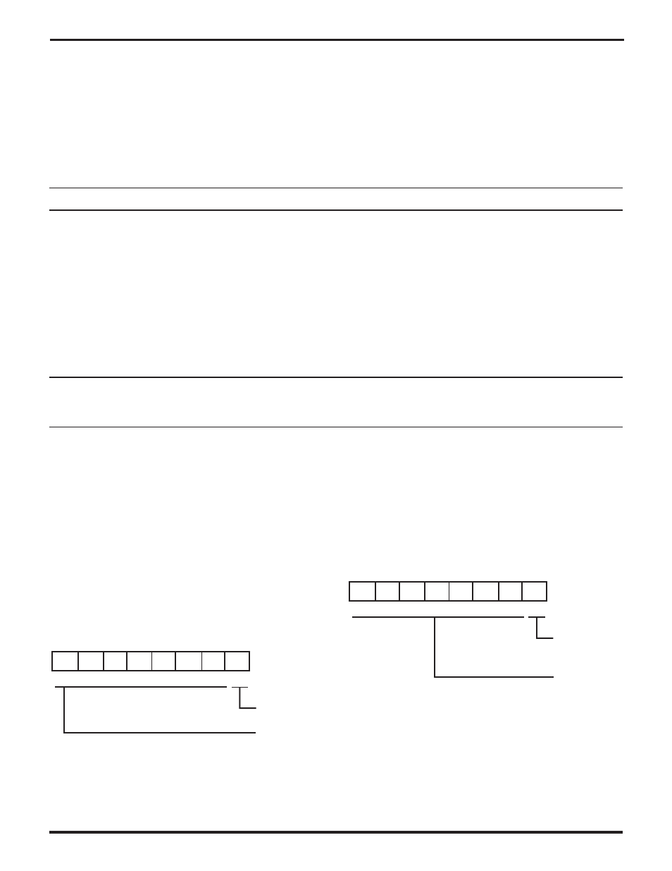
6.2.2.3 Interrupt Enable Register
D7-D4 Reserved Read as 0, should write to as 0.
D3-D0 IE3-IE0 (Interrupt Request Enable Flags)
These flags individually indicate if /INT3, /INT2, /INT1, or
/INT0 is enabled. Note that these flags are conditioned with
the Enable and Disable Interrupt instructions (with argu-
ments) (See Figure 6.1).
6.2.2.4 Assigned Vectors Base Register
D7-D1 AB15-AB9 (Assigned Vectors Base). The Interrupt
Register Extension, Iz, together with AB15-AB9, define the
base address of the assigned Interrupt vectors table in
memory space (See Figure 6-2).
D0 Reserved. Read as 0, should write to as 0.
AB15
7
AB14 AB13 AB12 AB11 AB10
AB9
--
0
0
0
0
0
0
0
0
0
Reset Value
AVBR: 00000018H
R/W
Assigned Vectors
Base
Reserved
Program as 0
Read as 0
Figure 6-2. Assigned Vectors Base Register
--
7
IE1
IE0
1
0
0
0
0
0
0
0
0
Reset Value
IER: 00000017H
Read Only
Interrupt Requests
Enable
Encoded Interrupt
Requests
--
--
--
IE2
IE3
Figure 6-1. Interrupt Enable Register