3 mimimum modbus support requirements, Modbus, Communication – AERCO Modbus Communications Manual User Manual
Page 8: Gf-114
GF-114
MODBUS
Communication
Chapter 1
OMM-0035_0C
USER MANUAL
Introduction & Description
Page
8 of 200 AERCO International, Inc. • 100 Oritani Dr. • Blauvelt, NY 10913 • Ph.: 800-526-0288 05/18/12
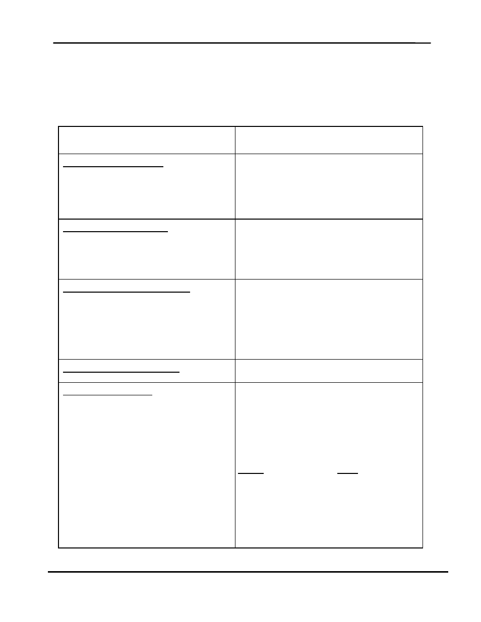
1.3 MIMIMUM MODBUS SUPPORT REQUIREMENTS
Implementation of a Modbus communication network utilizing the AERCO C-More Controller
and BMS/BMS II will be limited to the minimum support requirements listed in Table 1-1 which
follows. The remaining paragraphs in this Section provide more detailed descriptions for each
of the items listed.
Table 1-1: Modbus Communication and Support Requirements
CHARACTERISTIC
REQUIREMENT
Communication Medium:
EMS Master-To-BMS/BMS II/ACS Slave:
BMS/BMS II/ACS Master-To-C-More Slave:
EMS Master-To- C-More Slave:
RS232 (or RS485 With Optional Converter)
RS485, 2-Wire Differential Bus With Shield
RS485, 2-Wire Differential Bus With Shield
Allowable Cable Lengths:
RS232:
RS485:
PWM:
50 Feet, Maximum
4,000 Feet, Maximum
1,000 Feet, Maximum
Address Support From Master:
BMS/BMS II/ACS:
C-More Controller (Slave):
Broadcast Messages:
128 to 247 (From a Master EMS)
1 to 127 (From Master BMS/BMS II/ACS or
EMS)
Address 0 is Reserved for Broadcast
Messages
Transmission Mode Support
RTU (Remote Terminal Unit)
Timing Specifications:
Baud Rate:
Message Framing:
Character Framing:
Heartbeat Timeout:
Fixed at 9600 For C-More
Adjustable For BMS/BMS II/ACS: 2400, 4800,
9600, 14.4k, 19.2k
Default = 9600
Silent period of at least 3.5 character times
Before first character and After last character of
message
No more than 1.5 character times of silence
between received and transmitted characters
Fixed at 10 seconds For C-More
Adjustable For BMS/BMS II/ACS: 5 to 240
Seconds