Modbus, Communication, Gf-114 – AERCO Modbus Communications Manual User Manual
Page 21
Chapter 2
MODBUS
Communication
GF-114
Standard Register Assignments
USER MANUAL
OMM-0035_0C
05/18/12 AERCO International, Inc. • 100 Oritani Dr. • Blauvelt, NY 10913 • Ph: 800-526-0288
Page
21 of 200
2.3 BMS/BMS II CONTROLLER STANDARD REGISTER
ASSIGNMENTS
2.3.1 BMS/BMS II Controller Standard Input Register Assignments
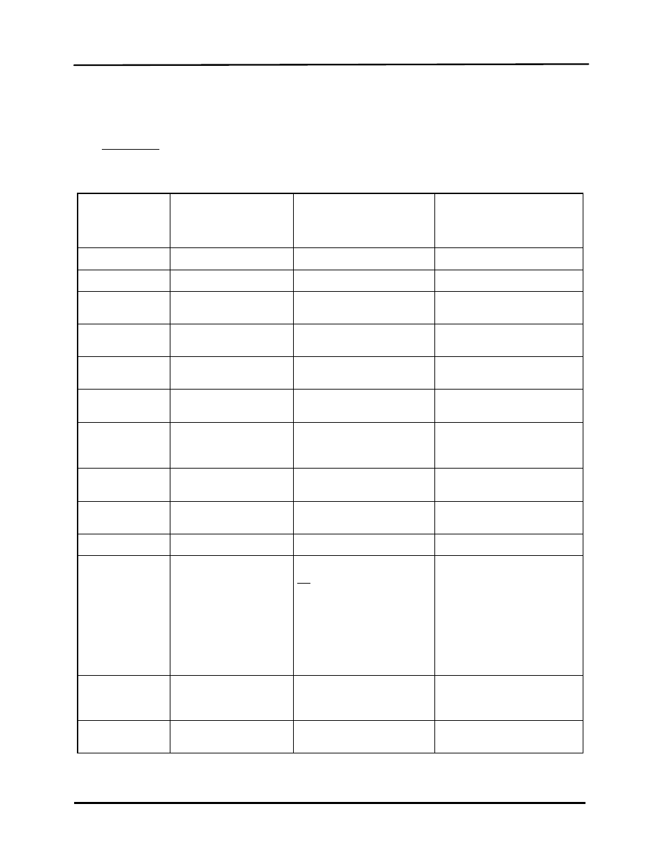
The Read Only Input Register address assignments for the BMS/BMS II are listed in Table 2-3
which follows:
Table 2-3: BMS/BMS II Standard Input Register Address Mapping
Modbus Data
Address
Decimal (Hex)
Menu Item
Units and Range
Default/
Comments
0 (0x0000)
(Reserved)
1 (0x0001)
Header Temperature
40 to 220°F
2 0x0002)
Outside Air
Temperature
-60 to 120°F
3 (0x0003)
Indoor Air/Return
Temperature
40 to 220°F
Indoor Air Temp = BMS
Return Temp = BMS II
4 (0x0004)
Fire Rate Out
0 to 100%
(out to boilers)
5 (0x0005)
Header Set
Temperature
40 to 220°F
6 (0x0006)
Network Address
128 to 247
Default = 128
(If Address = 0, BMS/ BMS II
is Off-Line as a Slave)
7 (0x0007)
Total Boilers Fired
0 to 40 (for BMS)
0 to 32 (for BMS II)
8 (0x0008)
Total Boilers On Line
0 to 40 (for BMS)
0 to 32 (for BMS II)
9 (0x0009)
(Reserved)
10 (0x000A)
Fault/Message Code
0 to 65535
Bit:
0 = Outside Air Sensor
1 = Header Sensor Error
2 = Interlock 1 Error
3 = Interlock 2 Error
4 = Indoor Air Sensor Error/
Return Sensor Error
5 = 4-20mA Input Error
Interpret Bit 4 as follows:
Indoor Air Sensor Error
applies to BMS.
Return Sensor Error applies
to BMS II.
11 (0x000B)
thru
15 (0x000F)
(Reserved)
16 (0x0010)
Lead Boiler Number
1 to 40 (for BMS)
1 to 32 (for BMS II)