1 introduction, 2 physical modbus rs485 network wiring connections, 1 bms slave to ems master wiring connections – AERCO Modbus Communications Manual User Manual
Page 57: Modbus, Communication, Gf-114
Chapter 4
MODBUS
Communication
GF-114
Hardware Setup & Installation
USER MANUAL
OMM-0035_0C
05/18/12 AERCO International, Inc. • 100 Oritani Dr. • Blauvelt, NY 10913 • Ph: 800-526-0288
Page
57 of 200
CHAPTER 4. MODBUS NETWORK HARDWARE SETUP
& INSTALLATION
4.1 INTRODUCTION
This Section provides basic information on planning and setup of a Modbus Communication
Network utilizing AERCO C-More Boiler Controllers and Boiler Management Systems (BMS/
BMS II) and AERCO Control System (ACS). It also provides basic information on Modbus
Network setup utilizing AERCO BMS/ BMS II/ACS or C-More Slaves with a Master EMS (or
BAS) provided by other manufacturers.
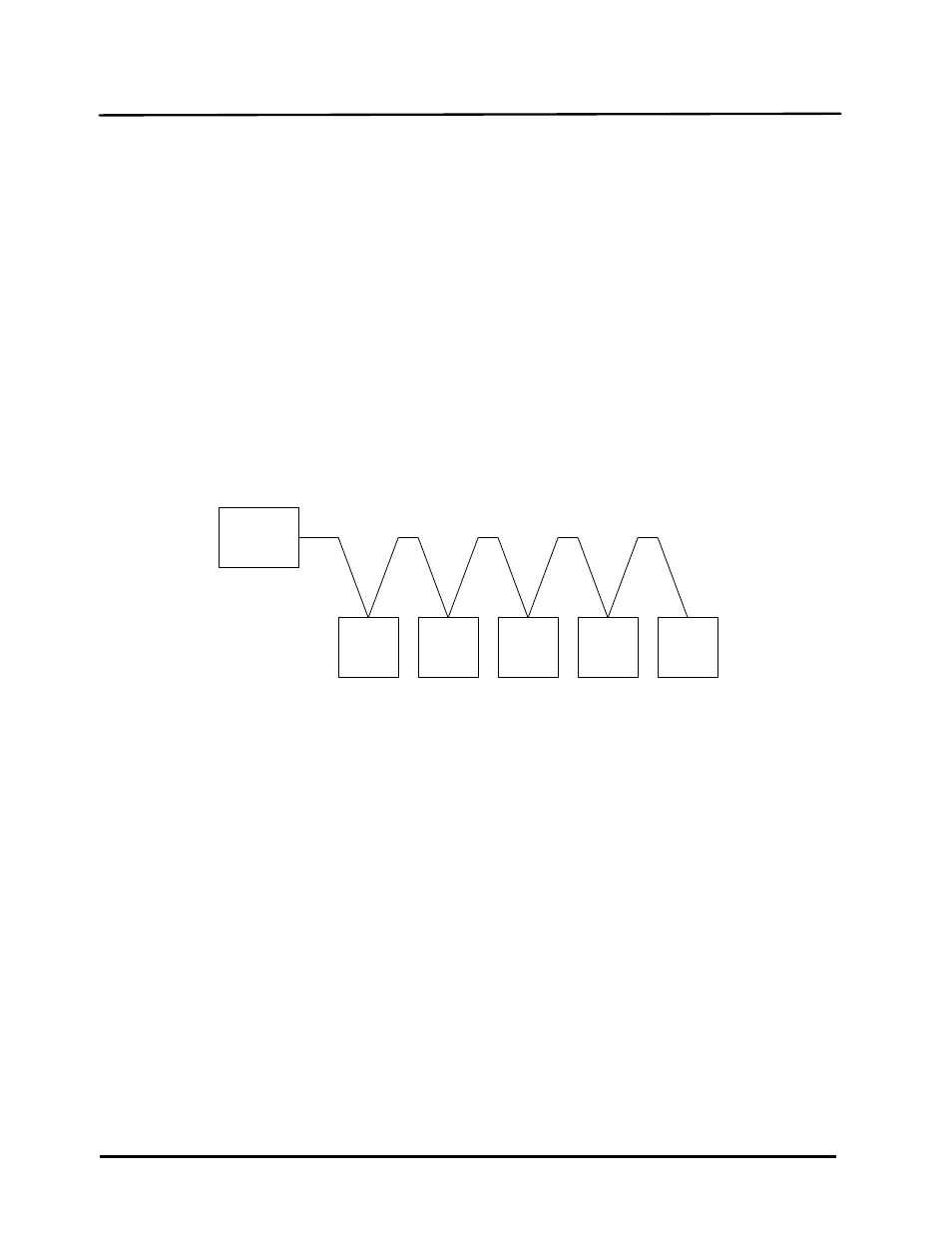
4.2 PHYSICAL MODBUS RS485 NETWORK WIRING CONNECTIONS
To properly perform combustion calibration, the proper instruments and tools must be used and
correctly attached to the unit. The following paragraphs outline the necessary tools and
instrumentation as well as their installation.
MASTER
SLAVE
#1
SLAVE
#2
SLAVE
#3
SLAVE
#4
SLAVE
#5
Figure 4-1: Typical Daisy-Chain Modbus/RS485 Network
The physical wiring connections for a Modbus Network utilizing an AERCO BMS/BMS II/ACS
and C-More Boiler Controllers should be made using shielded twisted-pair wire, from 18 to 24
AWG. Examples of suitable wire are: Belden #9841, #8761, #3105A, or equivalent.
The actual locations of the wiring connectors necessary for Modbus Network implementation
utilizing the AERCO BMS, BMS II, or ACS and C-More Boiler Controllers are provided in
paragraphs 4.2.1 and 4.2.2 respectively. Where necessary, connector pin-out information is also
provided.
4.2.1 BMS Slave To EMS Master Wiring Connections
Wiring connections between an EMS Master and an AERCO BMS Slave can be made at either
the RS232 (DB9) port on the left side of the BMS, or at the internal RS232 connector located on
the terminal board behind the connection cover on the BMS. These connections are shown in
Figure 4-2. The internal RS232 connections are used when interfacing with an EMS Master via
a conduit connection at the bottom edge of the BMS enclosure. If the internal RS232
connections are used, it is recommended that nothing be connected to the external RS232 (DB9)
port.
If the EMS Master being used contains only an RS485 port (2-wire or 4-wire), an RS485-to-
RS232 Converter is required. A BMS option is available with a built-in RS485-to-RS232
Converter to permit a conduit connection between the EMS and BMS. If the external RS232 port
on the left side of the BMS is used, a separate external converter is required.