Modbus, Communication, Gf-114 – AERCO Modbus Communications Manual User Manual
Page 67
Chapter 4
MODBUS
Communication
GF-114
Hardware Setup & Installation
USER MANUAL
OMM-0035_0C
05/18/12 AERCO International, Inc. • 100 Oritani Dr. • Blauvelt, NY 10913 • Ph: 800-526-0288
Page
67 of 200
CAUTION
The C-More Boiler Controller Printed Circuit Boards contain
electronic components that are sensitive to electrostatic discharge
(ESD). Prior to performing the following steps, put on an anti-static
wrist strap and connect the clip lead to earth ground. Failure to
observe this precaution may result in permanent damage to on-
board ESD-sensitive components.
4. Put on an anti-static wrist strap and attach the clip lead to earth ground.
5. From the back of the Panel Assembly (Figure 4-9), locate the RS485 DIP switches on the
PMC Board.
6. Refer to Figure 4-10 and set the “TERM” switch to the ON (Up) position.
7. Set the BIAS2 and BIAS1 switches to the ON (Up) position.
8. After the DIP switches have been set, reposition the Front Panel Assembly on the
chassis and secure it in place with the four screws.
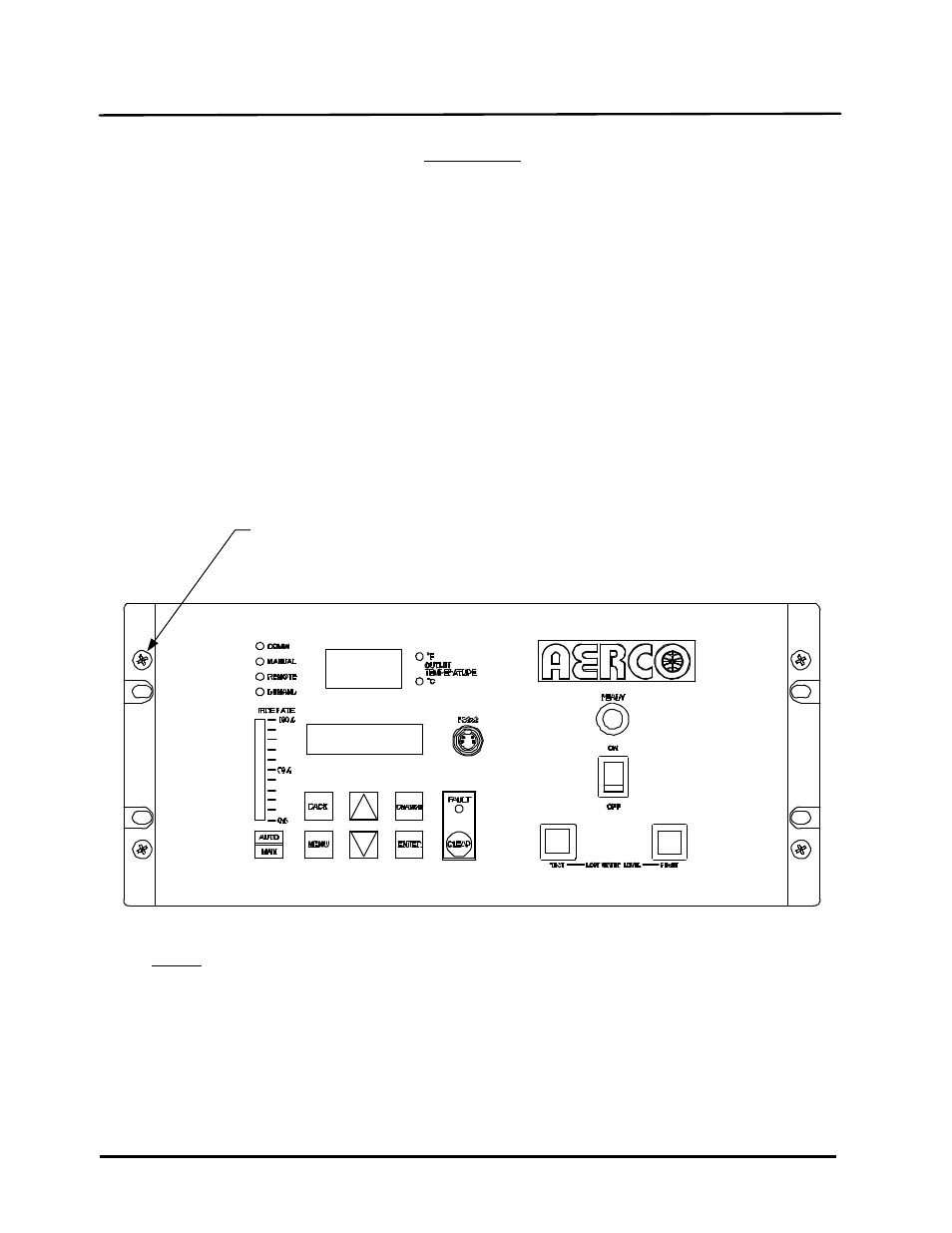
FRONT PANEL
SCREWS (4 PL)
THE C-MORE CONTROLLER MODEL SHOWN WITH A
HORIZONTAL PANEL CONTROL LAYOUT IS USED ON KC1000
BOILERS.
BENCHMARK BOILERS UTILIZE C-MORE CONTROLLERS WITH
A VERTICAL PANEL CONTROL LAYOUT.
NOTE:
Figure 4-8: C-More Control Panel - Front View