Modbus, Communication, Gf-114 – AERCO Modbus Communications Manual User Manual
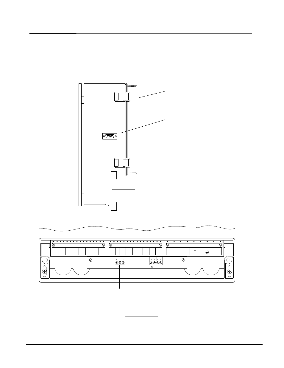
Page 58: View a – a (partial front view with cover removed), Figure 4-2: bms left side view, Chapter 4, User manual hardware setup & installation
GF-114
MODBUS
Communication
Chapter 4
OMM-0035_0C
USER MANUAL
Hardware Setup & Installation
Page
58 of 200 AERCO International, Inc. • 100 Oritani Dr. • Blauvelt, NY 10913 • Ph.: 800-526-0288 05/18/12
Simplified block diagrams showing the internal and external connection options between the
BMS and EMS are shown in Figure 4-3. Connector pinouts for the external RS232 (DB9-
Female) and internal RS232 connector are shown in Figure 4-4. In addition, Figure 4-4 shows
the pin assignments for the internal RS485 connector mounted on the BMS terminal board. This
connector is used to interface the boilers to the Modbus network.
1
9
RS232 PORT
(DB9 - FEMALE)
INTERNAL RS485 & RS232
CONNECTORS LOCATED
BEHIND COVER
(SEE VIEW A – A)
PANEL
COVER
A
A
L
N
AUX
FLT ALARM
SYS START
SET BACK
INT
2
INT
1
4-
20
MA
16
15
14
13
12
11
-10
+9
SHIELD
8
REF TEMP
HDR TEMP SEN
SHIELD
3
4
5
6
7
OUT AIR SEN
1
2
BLR 1
+1
-2
+3
-4
+5
-6
+7
-8
+9
-10
+11
-12
+13
-14
+15
-16
BLR 2
BLR 3
BLR 4
BLR 5
BLR 6
BLR 7
BLR 8
85-265 VAC
JP
4
JP
3
JP
2
+(B) -(A) SHLD
RXD TXD GND
RS485
TO BLRS
RS232
JP
11
JP
12
VIEW A – A
(PARTIAL FRONT VIEW WITH COVER REMOVED)
RS485
CONNECTOR
RS232
CONNECTOR
Figure 4-2: BMS Left Side View