Cub Cadet ISeries User Manual
Page 73
STEERING-HYDROGEAR
67
9e. Install both of the snap rings.
9f. Repeat for the right output bevel gear
assembly.
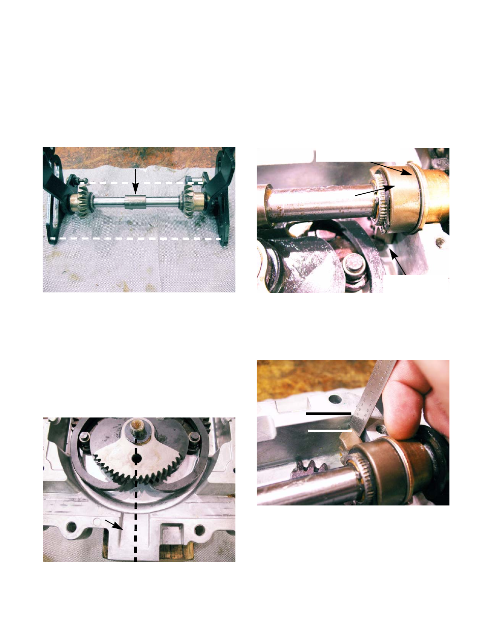
10.
Place both output bevel gear assemblies on the
bench, facing each other. With both assemblies
resting on the same points of the speed cam,
insert both shafts into the coupler.
See Figure 6A.61.
NOTE: The coupler has a master spline, but the
speed cam shafts do not. If both speed cams are
not resting on the same points when coupled
they are out of time.
11.
Insert the speed cam assemblies in the lower
housing.
•
Align the hole in the input sector gear with the
the center of the square recess at the front of the
lower housing. See Figure 6A.62.
Figure 6A.61
Coupler
Both speed cam are in line
Figure 6A.62
Recess
•
The bevel gears should face away from the input
sector gear.
•
The first tooth of each output bevel gear should
rest in the first valley the bevel gears in the bot-
tom of the lower housing.
•
The output bevel gear should have no play once
it is installed. If it does have play go back to step
9. See Figure 6A.63.
NOTE: To test proper gear timing; measure from
the farthest point of the output bevel gear to the
top of the housing. It should measure a 1/4” for
both sides. See Figure 6A.64.
NOTE: If one or both of the output bevel gears
are out of time; the steering rack will lose travel
on the affected side.
Figure 6A.63
Output bevel gear
Proper gear
Shimmed to a bind
timing
Figure 6A.64
1/4”