Cub Cadet ISeries User Manual
Page 114
STEERING-IVT
108
10.
With the pivot bar on a bench, the inboard steer-
ing gear and the tie rod can be serviced.
11.
Remove the tie rod by removing and discarding
the nut holding the tie rod ends to the in board
steering gear. See Figure 6B.92.
12.
Remove the inboard steering gear by removing
the bolt using a 9/16” wrench.
13.
Remove the steering king pins by:
13a. Removing the cotter pins in the bottom of
the king pins.
13b. Push the king pins out of the pivot bar.
See Figure 6B.93.
14.
Start re-assembling the pivot bar by inserting the
steering king pins into the pivot bar. Secure them
with new cotter pins. See Figure 6B.93.
15.
Install the axle assemblies.
16.
Place the outboard steering gears on the axles
and tighten to a torque of 100 - 150 in-lbs (11 -
17 Nm).
NOTE: The steering gears are marked LH and
RH. Make sure the LH is facing up on the left
hand side and that the RH is facing up on the
right.
17.
Apply a small amount of releasable thread lock-
ing compound such as Loctite® 242 (blue) to the
bolt for the in board steering gears. Align the tim-
ing marks on the inboard and outboard steering
gears and tighten the bolt that fastens the
inboard steering gears to a torque of 380 - 450
in- lbs (43 - 51 Nm).
NOTE: Make sure the bolts for the drag link and
tie rod are in the in place before installing the
steering gears.
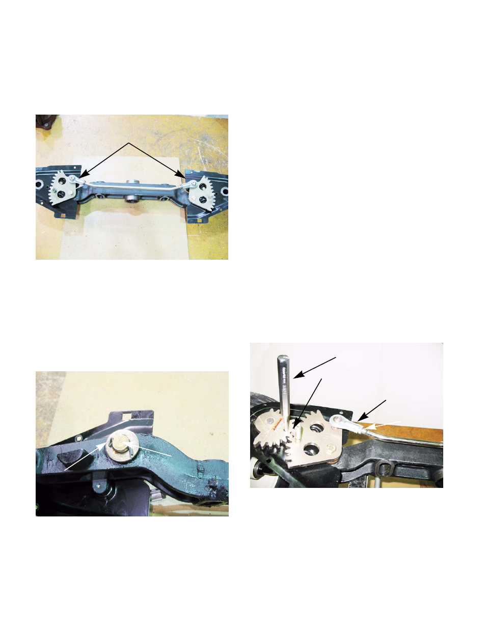
18.
Insert a 5/16” pin punch in the alignment holes of
the out board steering gears.
NOTE: Make sure they go all the way through
into the pivot bar to lock the gears in position.
See Figure 6B.94.
19.
Adjust the tie rod ends by loosening the jam nuts
and rotating the tie rod ends until they slide on
to the 1/4” bolts sticking up through the inboard
steering gears. Tighten the jam nuts to lock the
tie rod ends in place. See Figure 6B.94.
Figure 6B.92
Remove nuts
Figure 6B.93
King pin
Cotter pin
Figure 6B.94
5/16” pin punch
Timing marks
Adjust tie rod end
jam nut