Cub Cadet ISeries User Manual
Page 105
STEERING-IVT
99
8e. Install the snap ring.
8f. Repeat for the right output bevel gear
assembly.
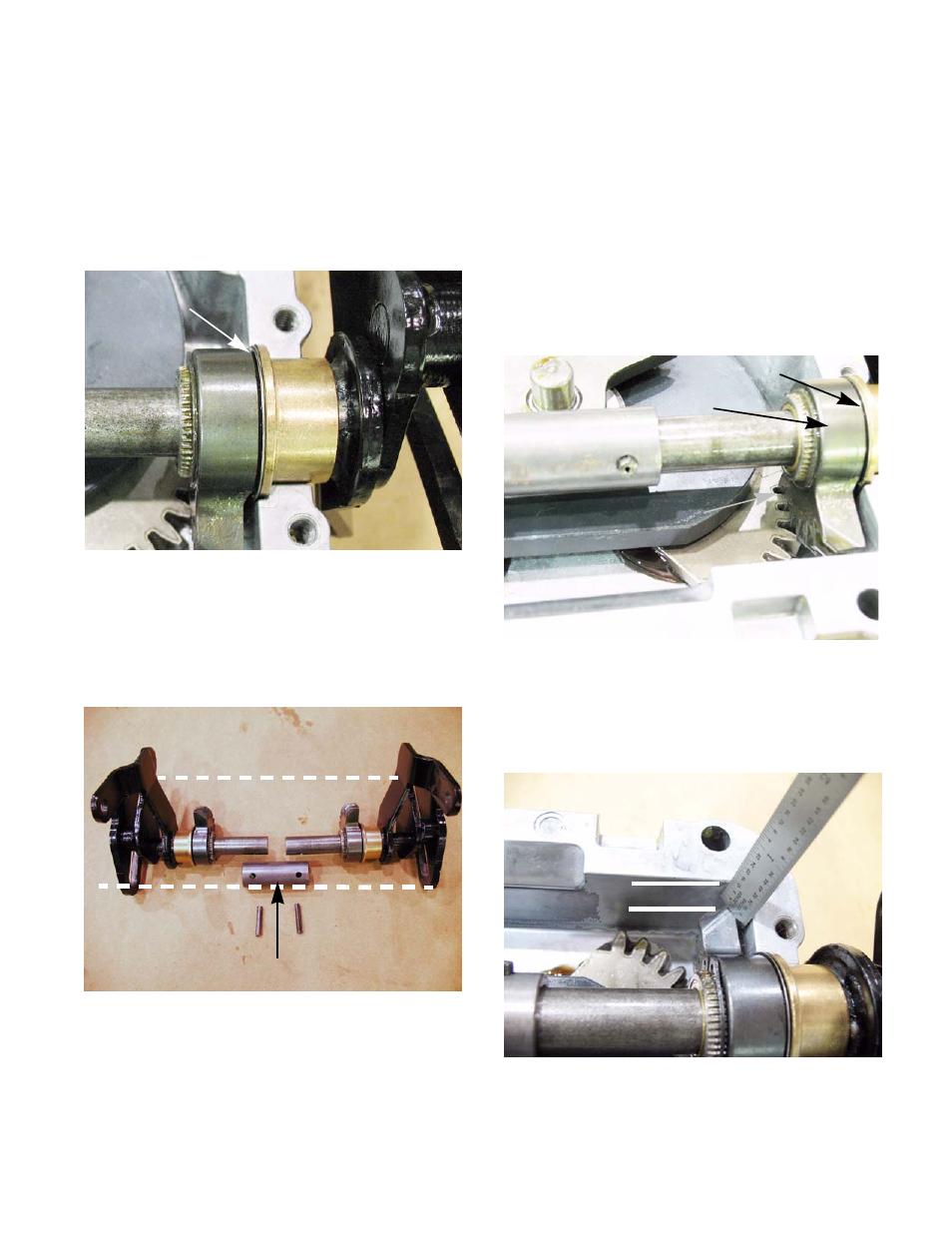
8g. Test fit each of the assemblies in the hous-
ing. The output bevel gear should have no
play between the housing and the snap ring
once it is installed. See Figure 6B.62.
9.
Place both output bevel gear assemblies on the
bench, facing each other. With both assemblies
resting on the same points of the speed cam,
insert both shafts into the coupler.
See Figure 6B.63.
10.
Drive the roll pins through the coupler and the
shafts to hold the assembly together.
11.
Insert the speed cam assemblies in the lower
housing.
Figure 6B.62
Shim to a bind
Figure 6B.63
Coupler
Both speed cam are in line
•
Line the hole in the input sector gear up with the
the center of the square recess at the front of the
lower housing.
•
The bevel gears should face away from the input
sector gear.
•
The first tooth of each output bevel gear should
rest in the first valley the bevel gears in the bot-
tom of the lower housing.
•
The output bevel gear should have no play once
it is installed. If it does have play, go back to step
9. See Figure 6B.64.
NOTE: To test proper gear timing; measure from
the farthest point of the output bevel gear to the
top of the housing. It should measure a 1/4” for
both sides. See Figure 6B.65.
Figure 6B.64
Output bevel gear
Proper gear
Shimmed to a bind
timing
Figure 6B.65
1/4”