Cub Cadet ISeries User Manual
Page 33
DRIVE SYSTEM-HYDROGEAR
27
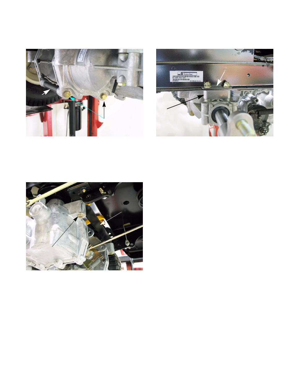
7.
Remove the two bolts that thread into the cross
tubes. See Figure 5A.11.
8.
Support the transmission to prevent it from fall-
ing while the mounting bolts are removed.
9.
Remove the bolt holding the transmission to the
torque bracket. See Figure 5A.12.
NOTE: There is a nut on the top side of the
torque bracket. Use a 7/16” wrench to hold it
while removing the bolt.
Figure 5A.11
Bolts
Cross truss
Bolt
Torque bracket
Figure 5A.12
10.
Remove the two bolts that fasten the transmis-
sion to the frame. See Figure 5A.13.
NOTE: The two transmission bolts pass through
a spacer and a reinforcing strap. When the bolts
are removed, the spacer and strap can be
removed. See Figure 5A.13.
11.
The transmission can now be removed from the
tractor.
12.
If replacing the transmission, remove the trans-
mission pulley and fan assembly.
13.
Remove the wheel hub assembly.
14.
Install the hub on the new transmission and
tighten to a torque of 420 - 480 in-lbs (47.5 -
54Nm).
15.
Install the transmission pulley and fan assembly
on the new transmission and tighten to a torque
of 300 - 460 in-lbs (34 - 52Nm).
16.
Install the transmission by following steps 1 - 11
in reverse order.
17.
Perform a neutral adjustment and wheel align-
ment by following the steps described in 6A:
Steering - HydroGear.
18.
Test drive the tractor in a safe area before
returning to service.
Figure 5A.13
Reinforcing strap
Spacer