Ammeters and specialized charging system testers – Cub Cadet ISeries User Manual
Page 133
ELECTRICAL SYSTEM
127
Self-powered continuity lights
Continuity lights can indicate whether a circuit is
complete or not, but they give no indication of resis-
tance. They are handy for finding point-break when
static-timing some older engines, but have largely been
replaced by DMMs.
There are some powered high-impedance test
lights on the market that have a continuity feature, and
some technicians like the fact that they can be less
bulky than a DMM.
Battery Jumper Cables
The obvious use of jumper cables is to jump-start
equipment to get it into the shop.
NOTE: This is not recommended for any fuel
injected Kohler-powered equipment.
A clever use of jumper cables: If the technician
suspects that there is resistance on the ground side of
the system, a quick-and-dirty test can be made using
jumper cables. See Figure 7.23.
•
Connect one cable clamp to the negative post of
the battery, and connect the clamp at the other
end of the same cable to the engine block.
•
If there is an immediate difference in starter
motor performance, use the voltage drop tech-
nique discussed later in this section to identify
the source of the resistance.
Figure 7.23
Inset:
Block connection
Inset:
Battery connection
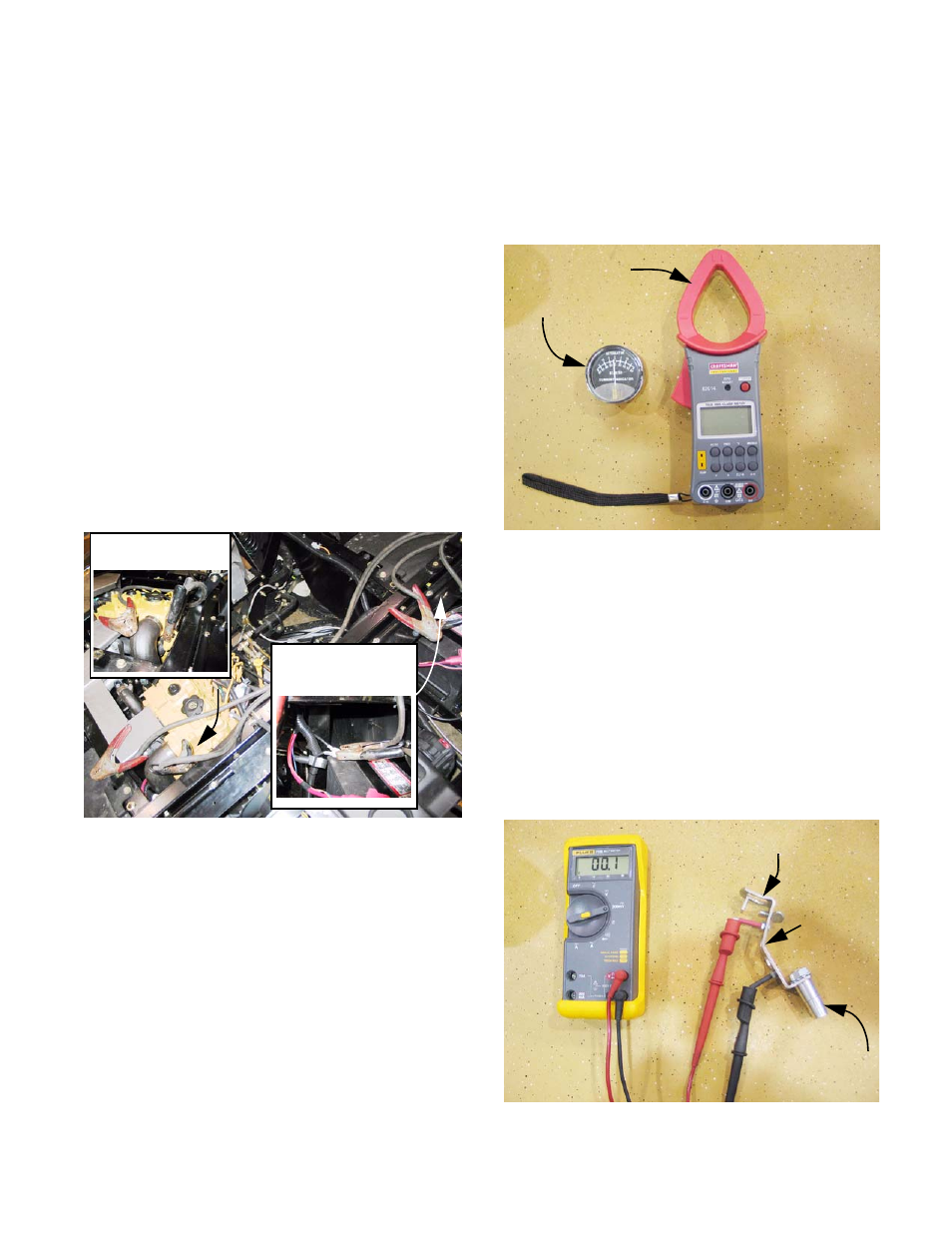
Ammeters and specialized charging system testers
Inductive ammeters are available in many forms.
Some are as simple as a gauge to be held against the
circuit in question when it is energized. The operating
principle is based on Ohm’s Law, as described earlier
in this section. See Figure 7.24.
There are two primary reasons to measure amper-
age. The first is to check the output of a charging sys-
tem or battery. The second is to check the performance
of a component that draws a substantial flow of power,
typically a motor or clutch.
Briggs and Stratton sells a DC Shunt that converts
amperage into a reading on the millivolt scale of a
DMM. Briggs and Stratton part # 19359 covers low
amperage systems, while part # 19468 tests higher
amperage systems. The operating principle is based
on Ohm’s Law, as described earlier in this section.
See Figure 7.25.
Figure 7.24
DMM with inductive
ammeter feature
Inductive ammeter
Figure 7.25
To negative
battery post
Connect to
battery end of
ground cable
DMM on
300Mv
scale
calibrated
resistance:
creates
amperage
reading