Wiring diagram or schematic, Fused jumper wires, Test lights – Cub Cadet ISeries User Manual
Page 132
ELECTRICAL SYSTEM
126
Amperage
Most DMMs have a very limited capacity to test
amperage (2-3 Amperes). When measuring current
flow, the meter must be connected in series with the
component to be measured. That means opening the
circuit and having the circuit go through the meter.
NOTE: Some meters have an inductive “Amp
clamp” accessory that can be used without
breaking the circuit.
IMPORTANT: Testing amperage beyond the
capacity of the meter can burn out an internal
fuse in some meters. The fuses can be expen-
sive.
Resistance
Set the meter for the “
Ω” scale.
•
Isolate the part of the circuit to be tested (discon-
nect it from the source of power).
•
Most auto-ranging meters will provide readings
on several scales. For outdoor power equip-
ment, the straight Ohm scale is most appropri-
ate. If a letter appears next to the W on the
screen of the DMM, it indicates different scales
of sensitivity.
•
“m” is micro-Ohms, a less sensitive scale that
effectively moves the decimal point three places
to the left of its location for plain
Ω
“K” is Kilo-Ohms, a more sensitive scale that
effectively moves the decimal point six places to
the right of its location for plain
Ω
“M” is Meg-Ohms, a more sensitive scale that
effectively moves the decimal point three places
to the right of its location for plain
Ω
•
A reading of “0” may be called “Continuity”.
A reading of “OL” may be referred to as “No
Continuity”.
•
Mistaken Ohm readings most frequently come
from bad technique. Poor connections between
the probes and the point to be read can throw-off
readings. False readings can be generated if the
technician touches both probes with their fingers
while taking the reading.
•
The meter has it’s own power source to measure
resistance. Connecting the meter to a compo-
nent that has current going through it will dam-
age the meter (usually beyond repair).
Wiring diagram or schematic
A wiring or a schematic diagram, and the ability to
read it are very important in troubleshooting a circuit.
The diagram shows how the circuit was designed and
what paths the electricity is suppose to flow.
Fused jumper wires
Fused jumper wires are handy to help find bad
grounds or to jump across switches for testing pur-
poses.
Test lights
Test lights are used as a quick way to verify voltage
at a point in a circuit. Like DMMs, they come in a wide
variety from many manufacturers.
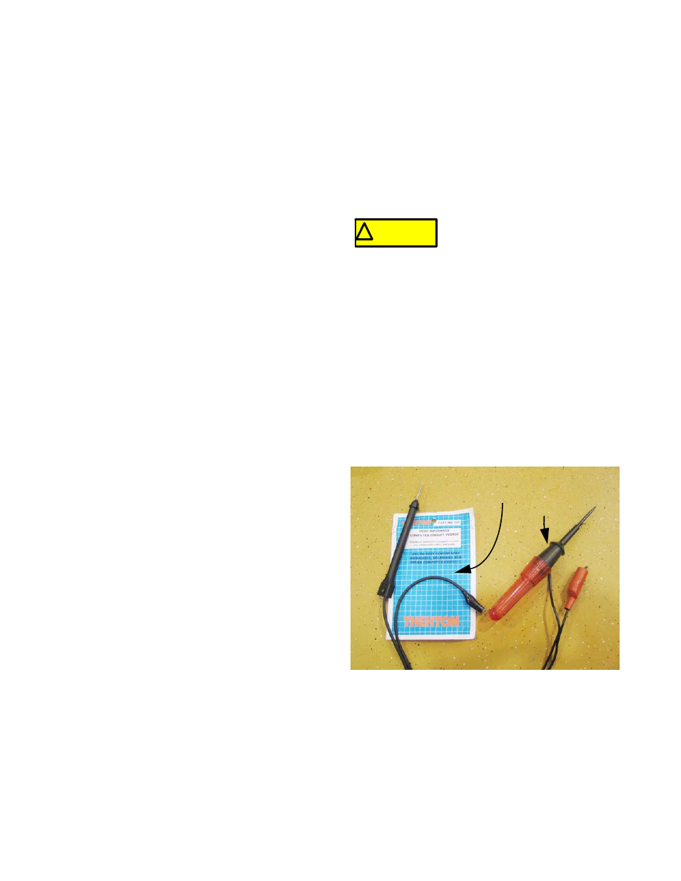
The most basic test lights simply use the current
being checked to light an incandescent lamp. These
should not be used on any equipment that has or may
have solid-state circuitry. The power necessary to light
the bulb is more than many solid-state circuits were
designed to handle. Components will be destroyed in
the process of testing them. See Figure 7.22.
IMPORTANT: Do not use a test light on an I-
series tractor. It can damage the RMC module.
IMPORTANT: If a test light is used at all, it
should have “high-impedance”, indicating that it
only takes a sample of the electricity being
tested, and illuminates an LED to indicate the
presence of power.
NOTE: Some high impedance test lights are
capable of indicating whether the current being
sampled is AC or DC.
! CAUTION
! CAUTION
Only use fused jumper wires. If
there is a short in the circuit, using
an unfused jump could damage
components in the circuit.
Figure 7.22
Hi impedance test light: Incandescent
GOOD test light:
CAUTION