Cub Cadet ISeries User Manual
Page 59
STEERING-HYDROGEAR
53
3.
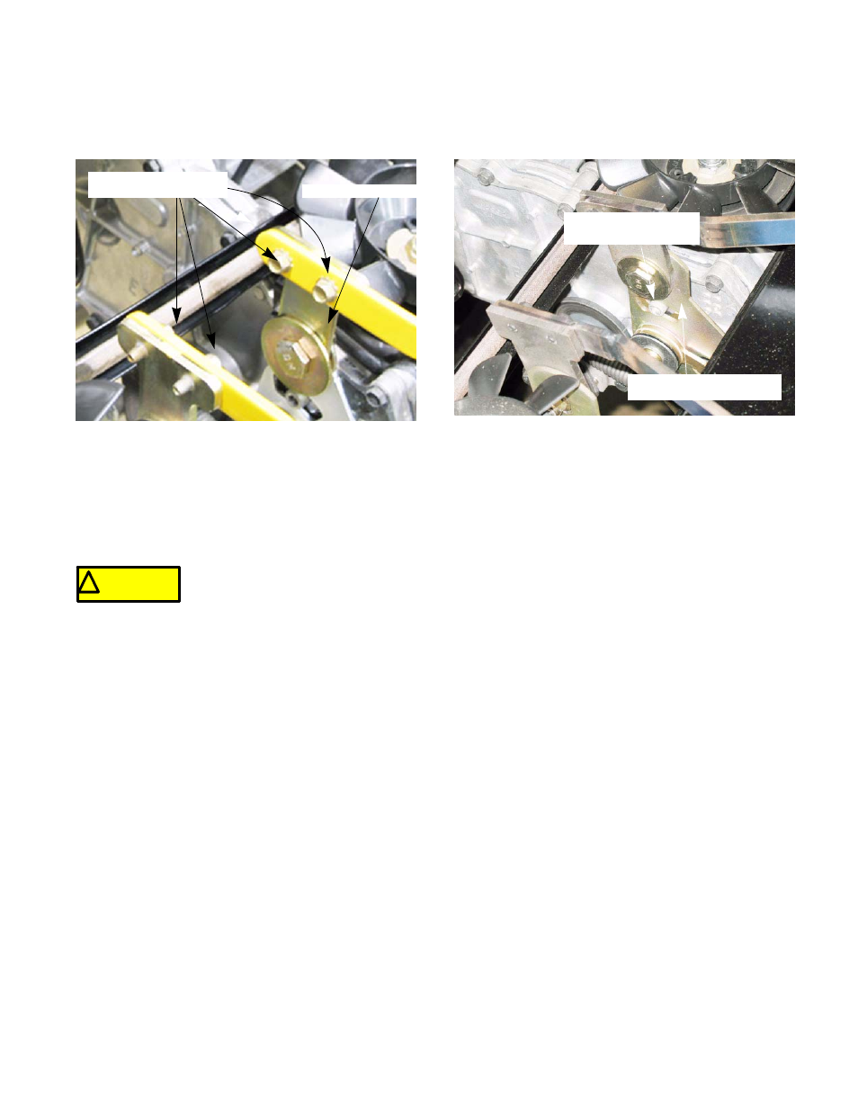
Loosen the two screws that connect each drive
control link to the shifter T-plate on each trans-
mission. See Figure 6A.11.
NOTE: Feel the shifter T-plate, it should be free
of any input from the transmission links. If ten-
sion is felt there, disconnect the links completely.
4.
While sitting in the seat, start the tractor and run
it at full throttle. Release the brake.
5.
Check the rear wheels.
NOTE: The rear wheels should not turn. If either
wheel turns, adjust the transmission for neutral
by:
Figure 6A.11
Loosen these screws
Shifter T-plate
! CAUTION
! CAUTION
The tractor engine and drive system
must be operated to complete this
procedure.
Confirm that no hazards will be incurred by running the
engine or operating the drive system
5a. Loosen the socket head cap screw in the
slot of the shift selector plate.
See Figure 6A.12.
NOTE: It is not necessary to remove the fender
for this step. The fender was removed in this
photo for clarity.
NOTE: Only loosen the screws on the side that
creeps.
5b. With the tractor still running, move the shift
selector plate until the wheel stops moving.
NOTE: For the best zero-turn performance, Set
the selector plate to the reverse side of the neu-
tral band (region where the transmission is in
neutral).
5c. Tighten the socket head cap screw.
NOTE: Leave the transmission links loose until
the wheels are aligned.
6.
Perform the wheel alignment by following the
procedures described in the next section of this
manual.
Figure 6A.12
Loosen this bolt
Shift selector plate