Cub Cadet ISeries User Manual
Page 104
STEERING-IVT
98
7.
Insert the input sector gear into the internal cam.
NOTE: The input sector gear and the internal
cam have a master spline to time the two to
each other. See Figure 6B.58.
8.
Assemble the output bevel gear assemblies.
8a. Insert the shaft of the left speed cam into the
left output arm. See Figure 6B.59.
8b. Place a bushing over the output arm with
the flange facing away from the arm.
See Figure 6B.59.
8c. Place a .030” shim (or a wave washer if it
came with one) over the output arm.
See Figure 6B.59.
NOTE: The bevel gear needs to be shimmed to
a bind. That means that once the assembly is
installed in the lower housing, there is zero play
between the bushing and the bevel gear. It may
take a few attempts to get the shims correct.
NOTE: On later production models, the shims
were replaced a wave washer between the
bushing and the output bevel gear.
8d. Place the output bevel gear on the output
arm with the chamfer facing away from the
hydro arm. See Figure 6B.60.
NOTE: The output arms and output bevel gears
have master splines to time them to each other.
See Figure 6B.61.
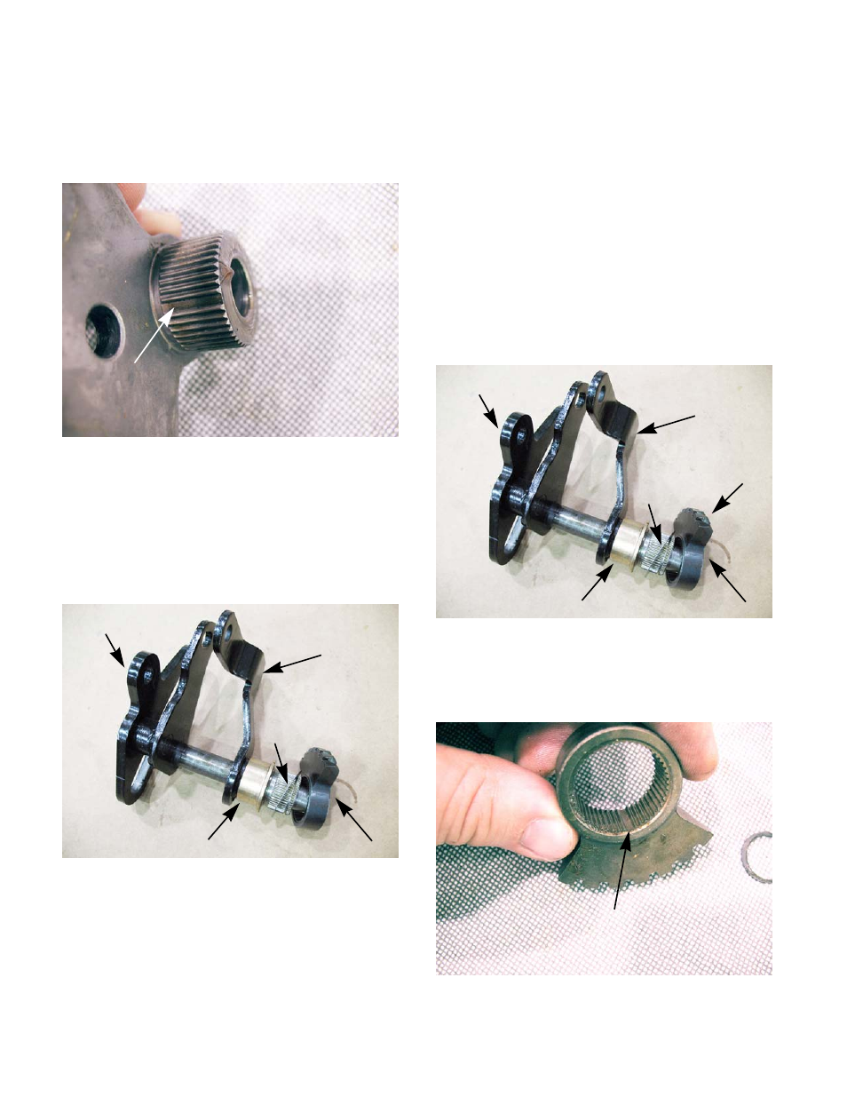
Figure 6B.58
Master
spline
Figure 6B.59
Bushing
Shim
Output bevel gear
Speed cam
Output arm
Figure 6B.60
Bushing
Shim
Output bevel gear
Speed cam
Output arm
Chamfer
Figure 6B.61
Master spline