Cub Cadet ISeries User Manual
Page 118
ELECTRICAL SYSTEM
112
information and the proper tools, a technician
should be able to efficiently diagnose most elec-
trical problems.
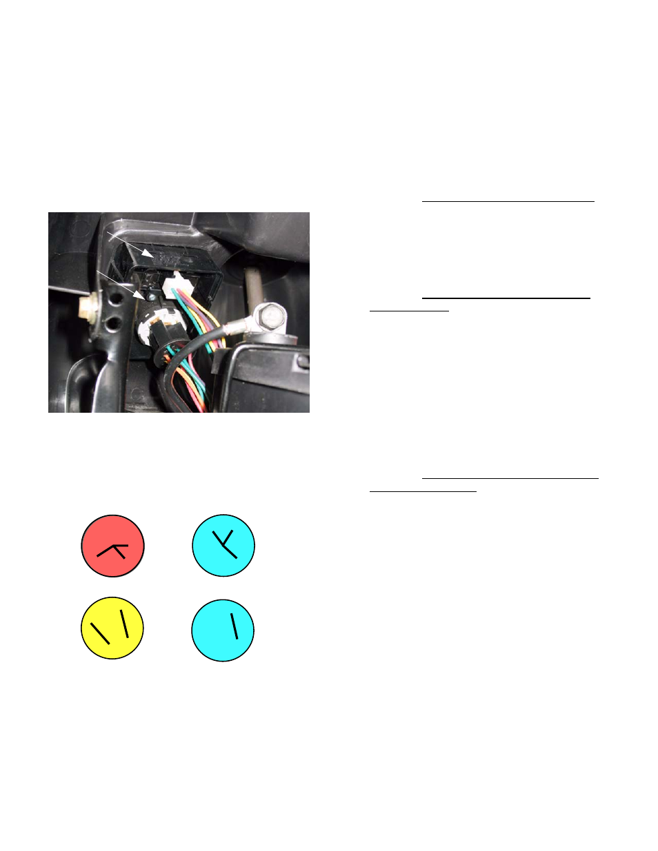
2.
Key switch
The Key Switch is similar to those used in a vari-
ety of MTD applications since 1999. The difference in
this case is that it is incorporated in the same housing
as the RMC module; the two items are not available
separately. See Figure 7.1.
2a. In the OFF position, continuity can be found
between the M, G, and A1 terminals.
See Figure 7.2.
•
M is connected to the magneto by a yellow wire,
G is connected to ground by a green wire, and
A1 is connected to the after fire solenoid.
NOTE: In the OFF position, the magneto primary
windings are grounded, disabling the ignition
system. The after-fire solenoid loses its power
from the B terminal. This turns off the fuel sup-
ply.
•
Symptom-engine runs with key in OFF position:
The key switch is not completing the path to
ground either because of an internal fault or a
bad ground connection elsewhere in the har-
ness. Check continuity between M, G, and A1
terminals with key switch in OFF position.
Check green wire for continuity to ground.
•
Symptom-loud “BANG” when key is turned to
the OFF position: The after-fire solenoid is not
closing, either because it is physically damaged
or the power is not being turned off. Check for
power at the solenoid. Check continuity between
G and A1 terminals. Check for no continuity
between A1 and the B terminals.
NOTE: If the engine is at an idle when the key is
turned off, fuel is drawn into the engine through
the idle ports of the carburetor by-passing the
fuel shut off solenoid. The raw fuel will travel
through the engine and ignite in the muffler
causing an after fire.
•
Symptom-Engine runs 3-5 seconds after key is
turned to OFF position: The after-fire solenoid is
turning off the fuel supply, but the ignition is con-
tinuing to operate. Check continuity between the
M and G terminals in the OFF position. Check
continuity from yellow wire connection all the
way to the spade terminal on the magneto.
2b. In the START position, continuity can be
found between B, S, and A1 terminals.
•
Battery power from the B terminal is directed to
the start circuit through the S terminal and to the
after-fire solenoid through A1.
Figure 7.1
Key
Switch
RMC Module
.H\VZLWFKVFKHPDWLF
/
0
$
$
*
6%
/
0
$
$
*
6%
/
0
$
$
*
6%
/
0
$
$
*
6%
2II
6WDUW
5XQZ50&
1RUPDOUXQ
Figure 7.2