Cub Cadet ISeries User Manual
Page 125
ELECTRICAL SYSTEM
119
8.
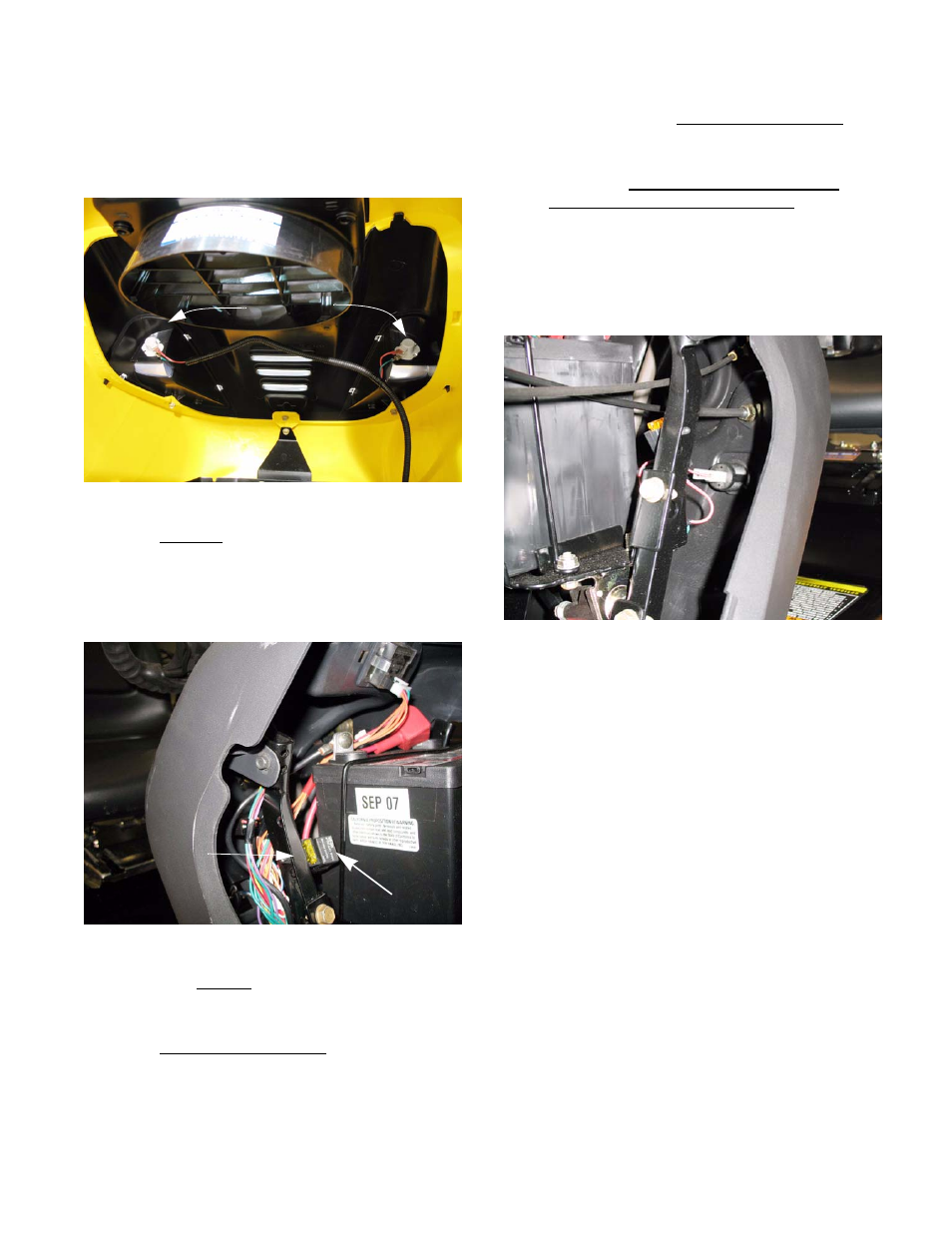
The lighting circuit is hot whenever the engine
is running. It does not draw from the battery, but
runs directly off its own circuit on the alternator.
See Figure 7.12.
•
The blue wire carries alternator current, the
green wire is a ground.
9.
The 20A fuse is located near the RMC module /
key switch assembly, under the dash panel.
See Figure 7.13.
•
The solid red wire feeds the fuse with power
picked up from the battery cable connection to
the “hot” post of the starter solenoid.
•
The red wire with white trace carries fused
power to the B terminal on the key switch.
Figure 7.12
Headlights
Figure 7.13
20 Amp fuse
PTO relay
•
There is a second red wire with white trace for
the auxiliary power point that will supply a 5 amp
service to the power point.
CAUTION: DO NOT PUT A CIGARETTE
LIGHTER IN THIS POWER POINT. this will
cause the fuse to blow and can seriously dam-
age the harness.
NOTE: The fuse for the auxiliary power point is
located above the starter solenoid.
See Figure 7.14.
•
A failed fuse will disable most of the tractor’s
electrical system.
NOTE: A fail fuse for the auxiliary power point
will only affect the power point.
•
Remember that a failed fuse has done its job of
protecting the rest of the circuit from an over-
load. If a fuse blows, figure out why and correct
the core problem before returning the tractor to
service.
10.
Refer to the engine manufacturer’s specifica-
tions to test the engine and charging systems.
11.
Ground issues: It is relatively easy to track
where power is on the positive side of the sys-
tem. The negative side is frequently neglected,
though it may account for just as many electrical
problems as the positive side.
Figure 7.14