Cub Cadet ISeries User Manual
Page 47
DRIVE SYSTEM-IVT
41
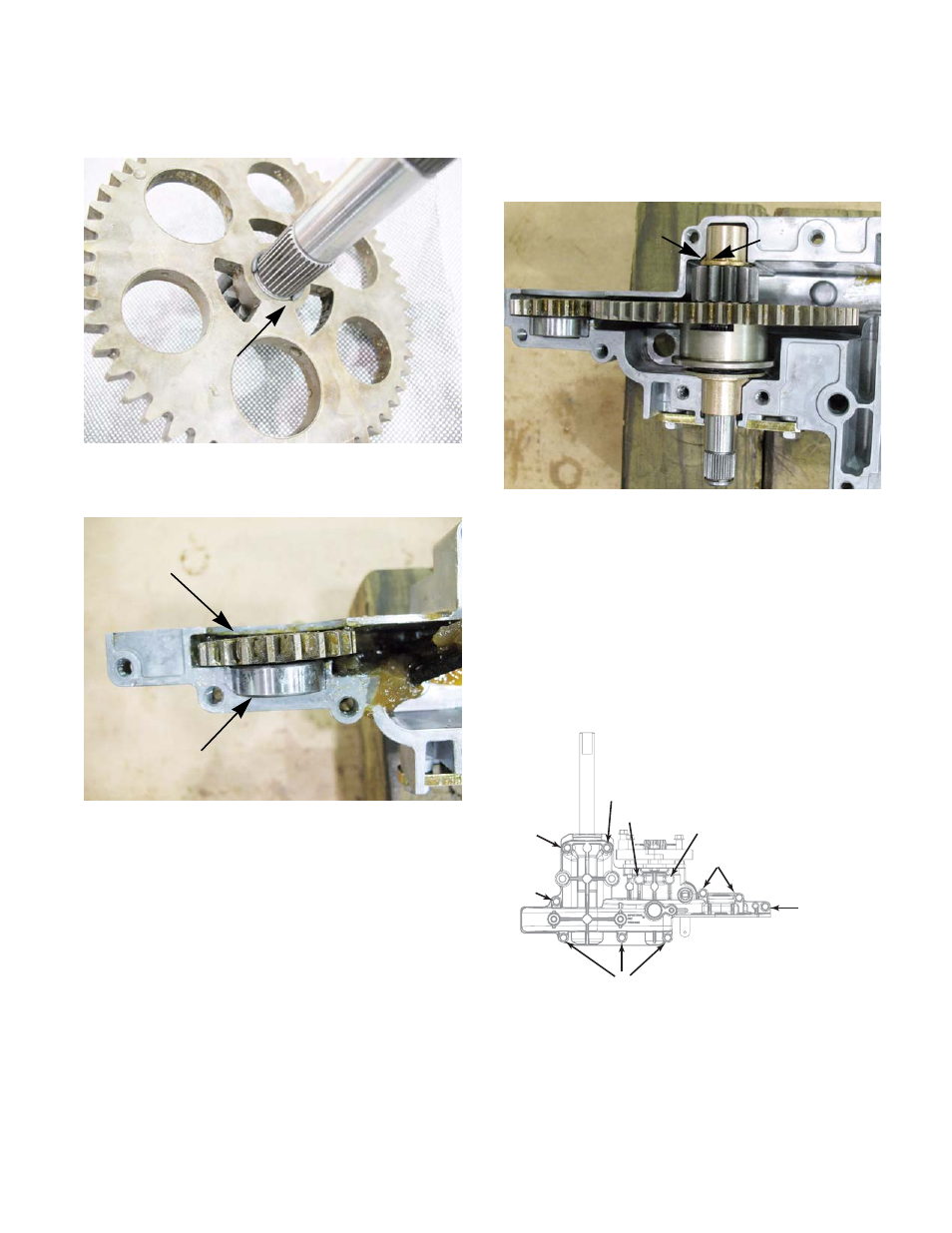
15.
Separate the spur gear from the brake shaft by
removing the retaining ring. See Figure 5B.38
16.
Remove the bearing. See Figure 5B.39
17.
Remove the input spur gear. See Figure 5B.39
18.
Clean and inspect all for the parts for damage
and signs of wear.
NOTE: Any parts that have damage or signs of
wear must be replaced.
19.
Re-assemble the drop axle by following the pre-
vious steps in reverse order.
Figure 5B.38
Retaining ring
Figure 5B.39
Input spur gear
Bearing
NOTE: When seating the bushings of the brake
shaft in the drop axle housing, the tab on the
bushings must seat in the notch in the housing.
NOTE: Apply Loctite #271 or an equivalent
threadlocker to the threaded section of the drive
axle. Tighten the nut that secures the drive gear
to a torque of 42 - 50 ft lbs. ( 56 - 68 Nm).
NOTE: Fill the drop axle with 10.5 ounces of
737-0300A Durina
TM
grease.
NOTE: The drop axle has four different length
screws securing the housings together.Figure
5B.51 shows were the different screws go.
NOTE: Tighten the screws to a torque of 90-120
in lbs. (10 - 14 Nm).
20.
Test drive the tractor in a safe area before
returning it to service.
Figure 5B.40
Tab
Notch
$ [´
% [´
& [´
' [´
$
&
&
%
%
'
&
'
Figure 5B.41