Cub Cadet ISeries User Manual
Page 135
ELECTRICAL SYSTEM
129
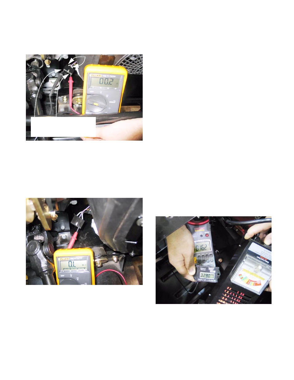
2b. Check the stator for resistance across the
leads. It should be in the range of 0.1 -0.2
Ω.
See Figure 7.28.
2c. With the engine stopped and the stator lead
unplugged from the voltage regulator / recti-
fier, check the resistance from each purple
stator lead to ground (engine block).
2d. The meter should indicate O.L., indicating
no continuity. See Figure 7.29.
Figure 7.28
Probes to white wires show
normal resistance through
stator windings: GOOD
White wires: stator
Figure 7.29
No continuity between
stator and ground:
GOOD
2e. Interpretation: If the ohm meter indicates no
continuity between the two the purple sta-
tor leads, there is a fault in the stator wind-
ings. If the ohm meter indicates continuity
between either purple stator lead and
ground, the stator windings are shorted to
ground.
NOTE: If there is an intermittent charging sys-
tem problem, perform these tests when the
engine is cold, and again when the engine is hot.
NOTE: Low voltage readings may also result
from poor test connections or low engine RPM.
3.
If the stator is good, test the amperage output
from the regulator / rectifier.
3a. Attach a DC shunt with DMM or an ammeter
capable of reading up to 25 amperes of DC
current. The most accurate point to take a
reading will be at the battery ground cable.
3b. The altenator should produce the rated cur-
rent at 3,600 RPM under an electrical load.
3c. Connect a load tester between the battery
terminals.
3d. With the engine running at 3,600 RPM,
energize the load tester to draw amperage
from the system.
3e. Read the amperage on the meter.
See Figure 7.30.
NOTE: Output varies with load. A fixed-load
battery tester can be used to apply enough load
to test the charging system out-put.
Figure 7.30