4 connection of proximity switches, Connection of proximity switches – Pilz PNOZ s30 24-240VACDC 2 n/o 2 n/c User Manual
Page 31
Commissioning
Operating Manual PNOZ s30
1001715-EN-13
31
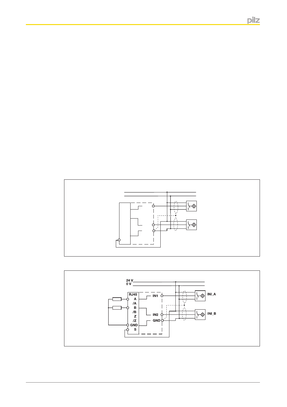
Connection of proximity switches
The following proximity switch combinations can be connected:
}
A: pnp, B: pnp
}
A: npn, B: npn
}
A: pnp, B: npn
}
A: npn, B: pnp
When connecting proximity switches please note:
}
Proximity switches can either be connected to terminals In1, In2 and GND or to tracks
A and B plus GND on the RJ45 socket.
}
Track S should be used to monitor the supply voltage (see drawing). A permitted volt-
age range can be entered in the menu.
}
Connect the proximity switch to 24 VDC of the power supply.
}
When connecting the proximity switches, please refer to the chapter entitled
"EMC-compliant wiring"
}
Invalid signals may occur with cable lengths >50 m. In this case we recommend that
you connect a resistor between the signal lines, as shown in the diagrams.
IN2
IN1
GND
24 V
0 V
INI_A
INI_B
RJ45
A
/A
B
/B
Z
/Z
GND
S
pnp proximity switch with resistor R = 10 kOhm
npn proximity switch with resistor R = 47 kOhm
6.1.4