2 rotary encoders, Rotary encoders – Pilz PNOZ s30 24-240VACDC 2 n/o 2 n/c User Manual
Page 26
Function description
Operating Manual PNOZ s30
1001715-EN-13
26
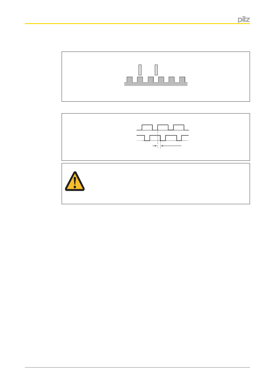
Proximity switch assembly:
Ini 1
Ini 2
Example pnp – pnp:
Proximity switch 1
Proximity switch 2
Energised
De-energised
Energised
De-energised
> 1 % of the period length
ATTENTION!
Appropriate installation measures should be taken to prevent a foreign body
coming between the signal encoder and the proximity switch. If not, the for-
eign body could cause invalid signals.
}
Please note the values stated in the technical details
}
The maximum frequency of the used encoders must be entered for a complete configu-
ration ("Encoder" Menu -> "Track AB" -> "Track AB fmax" / "Track Z" -> "Track Z
fmax").
Rotary encoders
}
The following rotary encoders can be used:
– TTL, HTL (single-ended or differential signals)
– sin/cos 1 Vss
– Hiperface
}
The rotary encoders can be connected with or without Z index (0 index)
}
The cable used to connect the rotary encoders must be shielded (see connection dia-
grams in the chapter entitled "EMC-compliant wiring").
}
A proximity switch can also be connected to track Z for monitoring broken shearpins
}
Track S can be used:
– To connect an encoder's error output
– To monitor voltages between 0 V and 30 V for a permitted upper and lower limit.
For example, the encoder's supply voltage can be monitored.
4.5.2