Attaching and removing the computer stand – Dell OptiPlex GX280 User Manual
Page 49
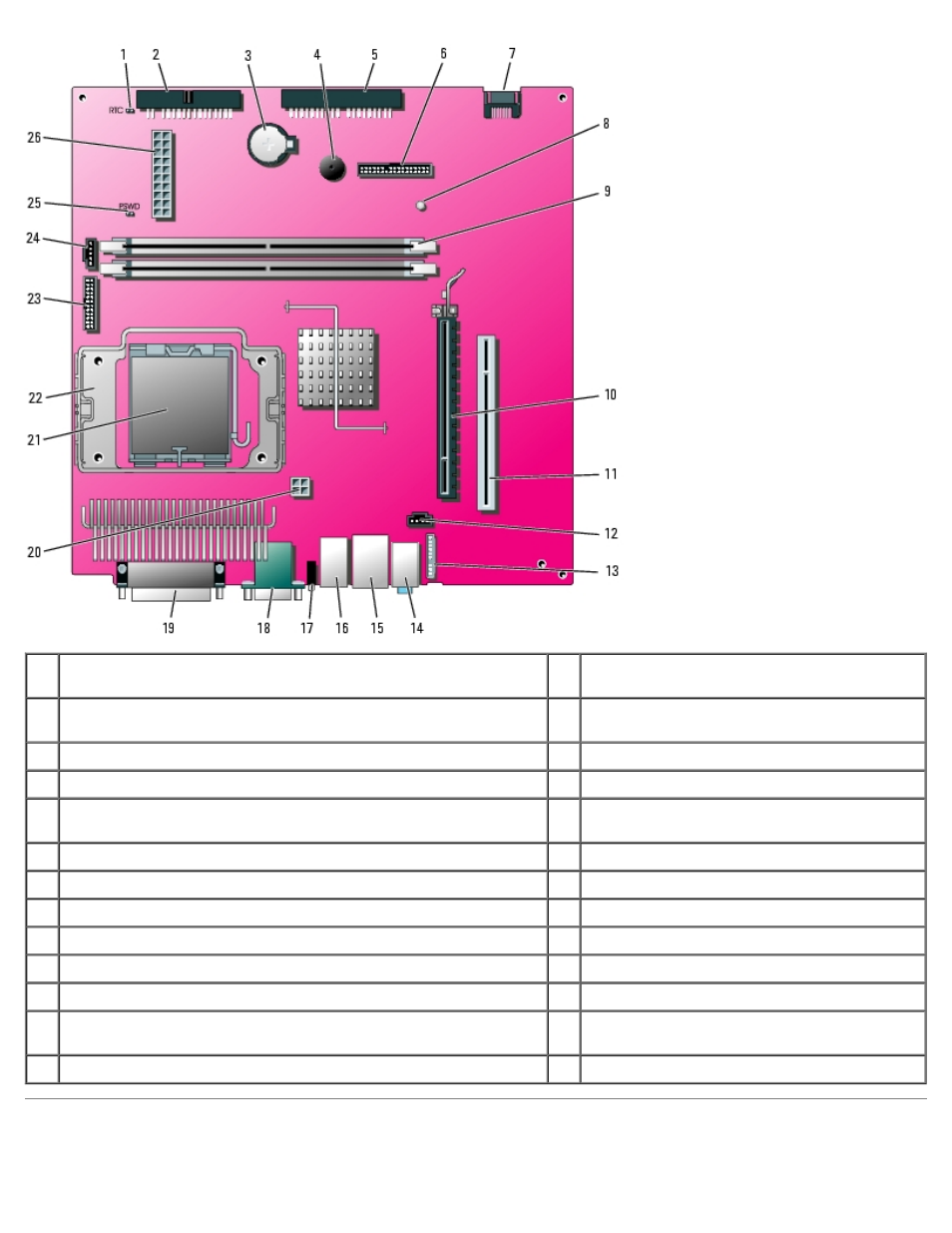
1
RTC reset jumper (RTCRST)
14 line-in, line-out, and microphone connectors
(AUDIO)
2
floppy drive connector (DSKT)
15 network connector (NIC) and USB connector
(USB2)
3
battery socket (BATTERY)
16 USB connectors (USB1)
4
internal speaker (SPEAKER)
17 diagnostic lights (DIAG LED)
5
CD/DVD drive connector (IDE)
18 serial port connector (SER1) and video
connector (VGA)
6
front-panel connector (FRONTPANEL)
19 parallel port connector (PAR)
7
serial ATA drive 0 connector (SATA0)
20 power connector (12VPOWER)
8
standby power light (AUX_PWR)
21 processor and heat-sink connector (CPU)
9
memory module connectors (DIMM1 and DIMM2)
22 heat sink/blower retention pad
10 PCI Express x16 connector (PEG)
23 serial port 2 connector (SER_PS2)
11 PCI riser connector (PCI)
24 fan connector (FAN)
12 CD drive analog audio cable connector for optional analog audio
cable (CD_IN)
25 password jumper (PSWD)
13 front-panel audio cable connector (FRONTAUDIO)
26 power connector (POWER)
Attaching and Removing the Computer Stand
- Inspiron 530 (2 pages)
- OptiPlex 755 (248 pages)
- OptiPlex 755 (622 pages)
- OptiPlex 755 (528 pages)
- OptiPlex 755 (82 pages)
- OptiPlex 755 (45 pages)
- OptiPlex 760 (76 pages)
- OptiPlex 760 (203 pages)
- OptiPlex 745 (212 pages)
- OptiPlex 745 (360 pages)
- OptiPlex 745 (428 pages)
- OptiPlex 780 (73 pages)
- OptiPlex 780 (40 pages)
- OptiPlex 780 (14 pages)
- OptiPlex 780 (89 pages)
- OptiPlex 780 (10 pages)
- OptiPlex 780 (74 pages)
- OptiPlex 780 (80 pages)
- OptiPlex GX620 (221 pages)
- OptiPlex GX620 (294 pages)
- OptiPlex GX620 (338 pages)
- Inspiron 530 (226 pages)
- OptiPlex 960 (Late 2008) (16 pages)
- OptiPlex GX260 (100 pages)
- OptiPlex GX260 (235 pages)
- OptiPlex FX160 (Late 2008) (20 pages)
- OptiPlex FX160 (Late 2008) (132 pages)
- OptiPlex FX160 (20 pages)
- OptiPlex 210L (128 pages)
- OptiPlex 210L (300 pages)
- OptiPlex 210L (258 pages)
- OptiPlex 210L (150 pages)
- OptiPlex 210L (130 pages)
- OptiPlex 320 (266 pages)
- OptiPlex 320 (356 pages)
- OptiPlex 320 (44 pages)
- OptiPlex 320 (140 pages)
- OptiPlex 320 (132 pages)
- OptiPlex 320 (312 pages)
- OptiPlex GX240 (182 pages)
- OptiPlex GX240 (144 pages)
- OptiPlex GX240 (121 pages)
- OptiPlex GX240 (86 pages)
- OptiPlex GX240 (283 pages)
- OptiPlex GX240 (298 pages)