Capacitor module connections – Rockwell Automation 2198-Hxxx Kinetix 5500 Servo Drives User Manual User Manual
Page 95
Rockwell Automation Publication 2198-UM001D-EN-P - May 2014
95
Connecting the Kinetix 5500 Drive System
Chapter 5
Capacitor Module
Connections
Follow these guidelines when wiring the 2198-CAPMOD-1300 capacitor
module:
• Wire relay output (MS) connections to the Logix5000 controller
(optional).
• Refer to
wiring example on
.
• Refer to
Kinetix 5500 Capacitor Module Status Indicators
for
troubleshooting the module status indicator and relay output.
• Refer to the installation instructions provided with your Bulletin 2198
capacitor module, publicat
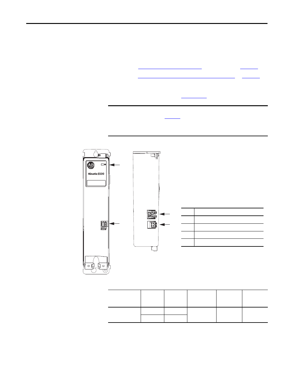
Figure 55 - Capacitor Module Wiring
Table 48 - Capacitor Module Connector Specifications
IMPORTANT
To improve system performance, run wires and cables in the wireways as
established in
Connections to the DC bus and 24V control power must be made with the
shared-bus connection system.
2
1
3
4
1
2
Kinetix 5500 Capacitor Module
Top View
Kinetix 5500 Capacitor Module
Front View
Item
Description
1
Module status (MS) connector (relay output)
2
Module status indicator
3
DC bus (DC) connector (under cover)
(1)
(2)
(1) The DC bus connector ships with a protective knock-out cover
that can be removed for use in shared-bus configurations.
(2) The shared-bus connector set for the capacitor module, catalog
number 2198-KITCON-CAP1300, is included for connection to the
upstream drive. Replacement kits are also available.
4
24V control input power (CP) connector
Capacitor Module
Cat. No.
Pin
Signal
Recommended
Wire Size
mm
2
(AWG)
Strip Length
mm (in.)
Torque Value
N•m (lb•in)
2198-CAPMOD-1300
MS-1
RELAY+
0.14…1.5
(28…16)
7.0 (0.28)
0.22…0.25
(1.9…2.2)
MS-2
RELAY-