Shared ac/dc example, Control power current calculations – Rockwell Automation 2198-Hxxx Kinetix 5500 Servo Drives User Manual User Manual
Page 220
220
Rockwell Automation Publication 2198-UM001D-EN-P - May 2014
Appendix C
Sizing Multi-axis Shared-bus Configurations
Shared AC/DC Example
If the required motoring power exceeds the available converter power sourced by
two leader drives, then connect all four drives as parallel converter drives. This
further increases the available converter power.
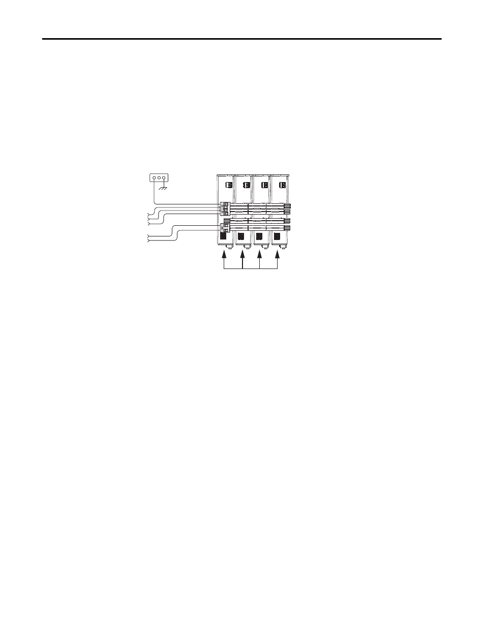
In this example, the same four 2198-H040-ERS drives are used, however, all four
are connected as parallel converter (leader) drives. The total converter power is
derated by 30%.
Figure 105 - Shared AC/DC Configuration
The available converter power to the system is (8.4 • 4) • 0.7 = 23.52 kW. In this
example, total motoring load must not exceed 23.52 kW. The available converter
power was increased by 180% over the same drives in shared DC configuration.
Control Power Current
Calculations
Kinetix 5500 servo drives and the Bulletin 2198 capacitor module have different
24V DC power consumption. Factors to consider when calculating the combined
current demand from your 24V DC power supply includes the following:
• Catalog number for each drive in the system
• Whether the motor or actuator includes the holding brake option
• Whether the system includes Bulletin 2198 capacitor modules (1 to 4
modules are possible)
Bonded Cabinet
Ground
Three-phase
Input Power
24V Input
Control Power
2198-H040-ERS
Converter Drives
DC Bus Connections