Establishing noise zones – Rockwell Automation 2198-Hxxx Kinetix 5500 Servo Drives User Manual User Manual
Page 39
Rockwell Automation Publication 2198-UM001D-EN-P - May 2014
39
Planning the Kinetix 5500 Drive System Installation
Chapter 2
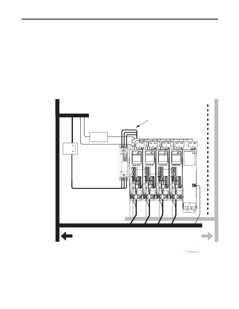
Establishing Noise Zones
Observe these guidelines when routing cables used in the Kinetix 5500 system:
• The clean zone (C) is beneath the drive system and includes the digital
inputs wiring and Ethernet cable (gray wireway).
• The dirty zone (D) is above and below the drive system (black wireways)
and includes the circuit breakers, 24V DC power supply, safety, and motor
cables.
• The very dirty zone (VD) is limited to where the AC line (EMC) filter
VAC output jumpers over to the drive (or first drive in multi-axis systems).
Shielded cable is required only if the very dirty cables enter a wireway.
Figure 16 - Noise Zones
(1) When space to the right of the drive does not permit 150 mm (6.0 in.) segregation, use a grounded steel shield instead. For
examples, refer to the System Design for Control of Electrical Noise Reference Manual, publicatio
.
(2) When 2198-H2DCK converter kit is used, feedback cable routes in the clean wireway.
(1)
C
C
D
D
VD
D
D
C
Dirty Wireway
Clean Wireway
Single Motor Cables
(2)
Circuit
Breakers
24V DC
Power Supply
AC Line Filter
(required for CE)
Kinetix 5500 Servo Drive System
(1)
(1)
Very Dirty Filter/AC Input Connections
Segregated (not in wireway)
Digital Inputs and
Ethernet Cables
Route single motor cables
in shielded cable.
Route registration and communication
signals in shielded cables.
Safety Cable
(2198-Hxxx-ERS drives only)
Module Status
24V Input