Rockwell Automation 2198-Hxxx Kinetix 5500 Servo Drives User Manual User Manual
Page 198
198
Rockwell Automation Publication 2198-UM001D-EN-P - May 2014
Appendix A
Interconnect Diagrams
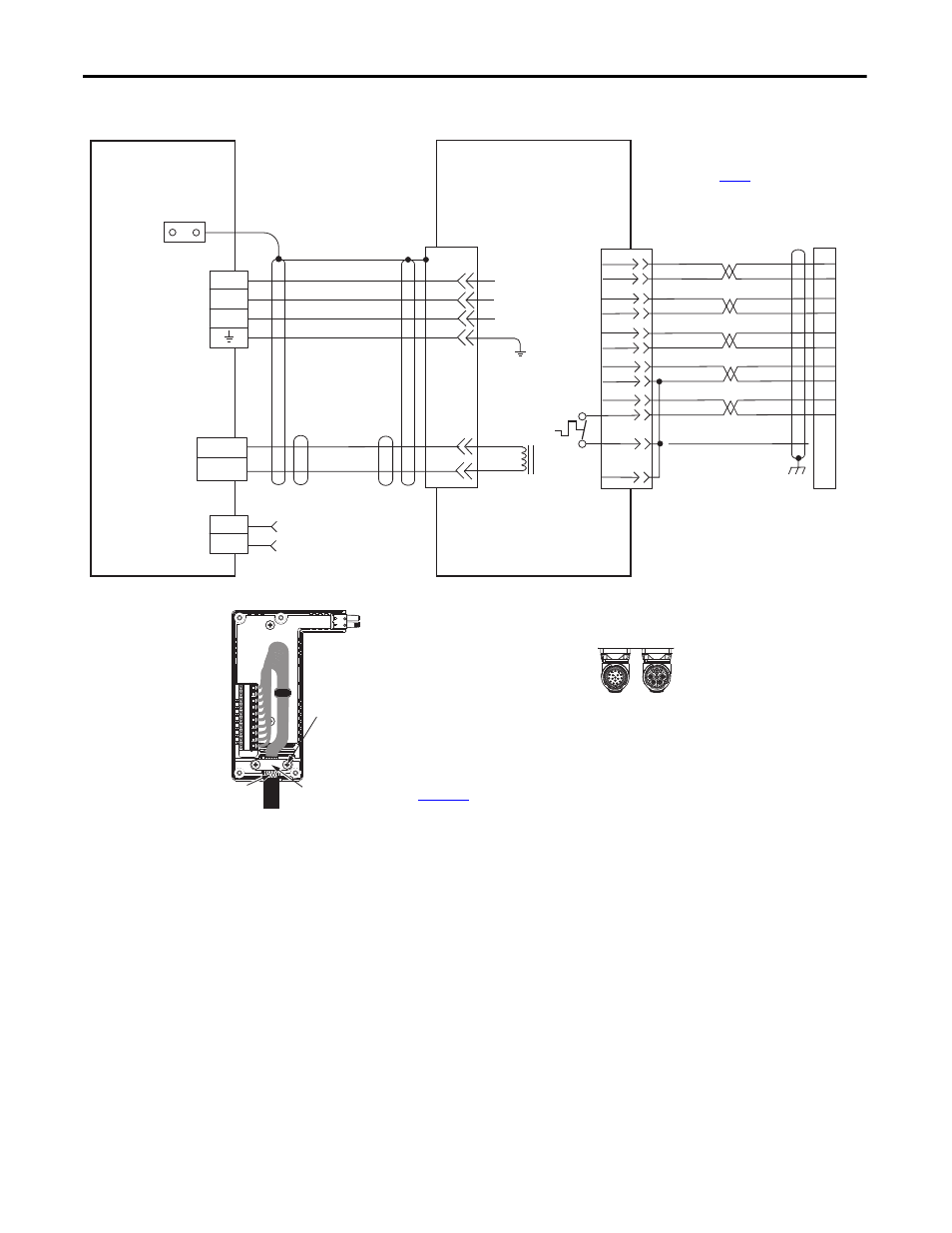
Figure 95 - Kinetix 5500 with MP-Series Linear Stages
C
B
A
MBRK+
MBRK-
F
G
U
V
W
SIN+
SIN-
COS+
COS-
DATA+
DATA-
+5VDC
ECOM
GREEN
WHT/GREEN
GRAY
WHT/GRAY
BLACK
WHT/BLACK
RED
WHT/RED
3
4
5
6
1
2
9
10
1
2
3
4
5
10
14
6
14
12
+9VDC
TS+
ORANGE
WHT/ORANGE
11
13
7
11
GND
TS-
COM
BLUE
D
U
V
W
1
2
D+
D-
1
2
4
3
2
1
MBRK +
MBRK -
Brown
Black
Blue
Green/Yellow
White
Black
Shield
14
11
10
7
6
5
4
3
2
1
Motor Brake
Motor Brake
(BC) Connector
Motor Power
(MP) Connector
MPAS-A/Bxxxxx-VxxSxA
Ballscrew Linear Stages with
High Resolution Feedback
Motor Feedback
(MF) Connector
Three-phase
Motor Power
Motor
Feedback
Thermostat
Grounding Technique for
Feedback Cable Shield
Cable Clamp
Exposed shield secured
under clamp.
Clamp Screws (2)
for note information.
2198-H2DCK Feedback
Converter Kit
Cable Shield
Clamp
Note 5
2198-Hxxx-ERSx
Kinetix 5500 Servo Drives
Refer to Hiperface to DSL Feedback Converter Kit Installation Instructions,
publication
onverter kit specifications.
Power Connector
Feedback Connector
SpeedTec DIN
Motor Connectors
2090-CFBM7DF-CEAAxx (standard) or
2090-CFBM7DF-CEAFxx (continuous-flex)
(flying-lead) Feedback Cable
Notes 11, 12, 13
2090-CPxM7DF-xxAAxx
(standard) or
2090-CPxM7DF-xxAFxx
(continuous-flex)
Motor Power Cable
Notes 11
Refer to DSL feedback converter kit
illustration (lower left)
for proper grounding technique.
2198-H2DCK
Hiperface-to-DSL
Feedback Converter Kit