Circuit diagrams – Rockwell Automation 1756-OF8H ControlLogix HART Analog I/O Modules User Manual
Page 62
62
Rockwell Automation Publication 1756-UM533C-EN-P - February 2011
Chapter 4
1756-IF8H HART Analog Input Module
For devices powered by individual supplies, when the ground potential of the
supplies is expected to differ, Differential mode is recommended. This prevents
ground loop currents from flowing between the supplies. However, the potential
difference allowable between the supplies must remain within the specified
limits.
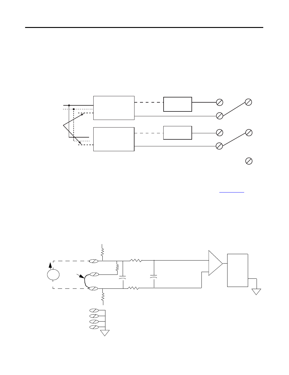
Figure 8 - Power Supplies with Isolated Grounds
Some devices, such as AC powered four-wire devices, are recommended to be
used in Differential mode only. It is best if differential and
input
types are not combined onto the same terminal block, that is, all should be
single-ended or all should be differential.
Circuit Diagrams
This section shows the 1756-IF8H module’s input circuit diagrams.
Figure 9 -
Simplified 1756-IF8H Current Input Circuit
Power Supply 1
HART
Device 1
HART
Device 2
Power Supply 2
Ground wire isolated
from each other
IN0+
IRTN-0
IRTN-1
RTN
IN1+
IN0-
IN1-
+
-
+
-
The low end of the terminal block pins are now isolated from each other
and the inputs can be configured as true differential inputs as long as the
voltage difference between them does not exceed 7V.
32140-M
0.01
μF
Analog to
Digital
Converter
22 K
Ω
10 M
Ω
RTN
RTN
RTN
RTN
-15 V
Jumper
+
-
0.01
μF
22 K
Ω
10 M
Ω
249
Ω
1/4 Watt
INO+
IRTN-O
INO-
+15 V
Differential
Current
Input
i