Connect the ungrounded end of the cable – Rockwell Automation 1756-OF8H ControlLogix HART Analog I/O Modules User Manual
Page 33
Rockwell Automation Publication 1756-UM533C-EN-P - February 2011
33
Module Installation Chapter 2
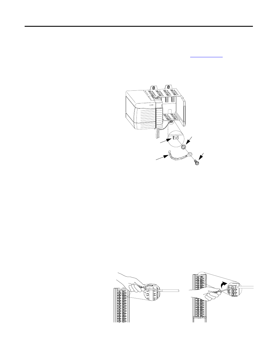
If you cannot ground at the field device, follow these steps.
1.
Prepare one end of the cable as shown in
Ground at an earth ground on the chassis.
Connect the drain wire to a chassis mounting tab. Use any chassis
mounting tab that is designated as a functional signal ground.
2.
Connect the insulated wires to the field device.
Connect the Ungrounded End of the Cable
Follow these steps to connect the ungrounded end of the cable to the clamp.
1.
Cut the foil shield and drain wire back to the cable casing and apply shrink
wrap.
2.
Connect the insulated wires to the RTB.
Chassis Mounting Tab
Drain Wire with Ground Lug
4M or 5M (#10 or
#12) Phillips Screw
and Star Washer (or
SEM screw)
4M or 5M (#10 or
#12) Star Washer
20918
Spring Clamp RTB
Cage Clamp RTB
a. Strip 10 mm (0.4 in.) maximum length
of wire.
b. Insert the screwdriver into the inner
hole of the RTB.
c. Insert the wire into the open terminal
and remove the screwdriver.
a. Strip 8.3 mm (0.33 in.) maximum length
of wire.
b. Insert the wire into the open terminal.
c. Turn the screw clockwise to close the
terminal on the wire.