Analog and hart pv – Rockwell Automation 1756-OF8H ControlLogix HART Analog I/O Modules User Manual
Page 184
184
Rockwell Automation Publication 1756-UM533C-EN-P - February 2011
Appendix A Tag Definitions
Analog and HART PV
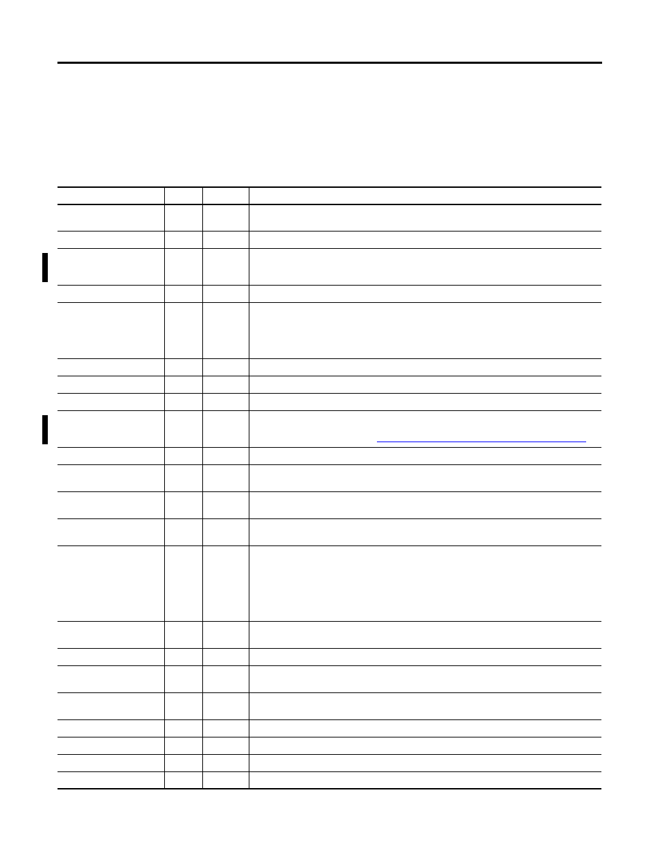
This table describes the input tags available in the Analog and HART PV
data format.
Table 68 - Analog Only (AB:1756_OF8H_HARTPV:I:1)
Member Name
Type
Style
Description
Channel Faults
(bits 9...15 unused)
INT
Binary
ChxFault
BOOL
Decimal
ChannelFaults.x, Indicates communication fault or fault condition from ChXStatus.
LoopOutputFault
BOOL
Decimal
ChannelFaults.8, This is a hardware fault where the module has detected that the power supply to
the isolated(analog) side of the board has failed(no power). It does not roll into any other bits. The
OK status indicator is set to solid red.
HARTFaults
SINT
Binary
ChxHARTFault
BOOL
Decimal
HARTFault.x
Indicates a problem with HART data from the field device on Channel x. Examples are HART not
enabled, HART device not connected, HART communication failure due to noise.
The following field device status conditions also cause this to be set: Device Malfunction,
PV Out of Limits, Loop Current Saturated, and Loop Current Fixed.
ModuleFaults
SINT
Binary
CalFault
BOOL
Decimal
ModuleFaults.1, 1756-IF8H module calibration failed.
Calibrating
BOOL
Decimal
ModuleFaults.2, Calibration in progress.
UpdatedStatusReady
BOOL
Decimal
ModuleFaults.3, Module has collected updated Additional Device Status from HART command 48.
This status can be retrieved by using the Read Additional Status service, 16#4C. For more
information about this service, see
Read Additional Status (Service Code = 16#4C) on page 125
AnalogGroupFault
BOOL
Decimal
ModuleFaults.7, Indicates a fault has occurred on any channel (any of ChannelFaults).
Ch0Status
SINT
Binary
Indicates various alarms on the analog signal. Also sets Ch0Fault for Overrange, Underrange,
and CalFault.
Ch0HLimitAlarm
BOOL
Decimal
Ch0Status:0 The analog output signal is being limited by the Ch0Config.HighLimit value.If
Ch0Config.LimitAlarmLatch is 1, alarm is retained until explicitly reset.
Ch0LLimitAlarm
BOOL
Decimal
Ch0Status:1 The analog output signal is being limited by the Ch0Config.LowLimit value.If
Ch0Config.LimitAlarmLatch is 1, alarm is retained until explicitly reset.
Ch0RampAlarm
BOOL
Decimal
Ch0Status:2 Rate of change in Ch0Data exceeds Ch0Config.MaxRampRate. Rate of change is
determined by the change in Ch0Data divided by the RPI period. Thus if a step change in Ch0
cannot be reached via the configured MaxRampRate within one RPI, then Ch0RampAlarm is set
to 1. If Ch0Config.RampAlarmLatch is 1, then Ch0RampAlarm remains set until explicitly reset
using CIP message even if the condition returns to normal. The CIP message can be sent via
MSG instruction in the Logix controller or from the RSLogix 5000 Module Properties Limit
dialog box.
Ch0InHold
BOOL
Decimal
Ch0Status:3 Channel holding its last output value, waiting for controller to match the value,
indicating that bumpless initialization of the control loop is complete.
Ch0CalFault
BOOL
Decimal
Ch0Status:4 Fault during calibration of channel 0.
Ch0NotANumber
BOOL
Decimal
Ch0Status:5
Ch0Data is not a valid floating point number.
Ch0OpenWire
BOOL
Decimal
Ch0Status:7 Only valid in current mode (example 4…20 mA). 1 indicates no current is flowing,
probably due to open circuit.
Ch1Status
SINT
Binary
Indicates various alarms on the analog signal. Also sets Ch1Fault.
Ch2Status
SINT
Binary
Indicates various alarms on the analog signal. Also sets Ch2Fault.
Ch3Status
SINT
Binary
Indicates various alarms on the analog signal. Also sets Ch3Fault.
Ch4Status
SINT
Binary
Indicates various alarms on the analog signal. Also sets Ch4Fault.