G-file considerations for configuring remote i/o, Crossing logical rack boundaries – Rockwell Automation 1747-BSN Backup Scanner Module User Manual
Page 74
Publication 1747-UM010B-EN-P - September 2003
5-12 Configuration and Programming
G-File Considerations For
Configuring Remote I/O
You should understand the following information before you
configure your scanner’s G file.
•
You can only change the RIO configuration by modifying the G
file while offline in your program file. Your application program
cannot access the G file, nor can you modify it while online with
your programming device. However, your SLC control program
can dynamically inhibit and uninhibit RIO devices via the M0
file.
•
RIO devices larger than 1 logical rack appear as multiple devices
on the RIO link. Refer to the Crossing Logical Rack Boundaries
section below.
•
The address and size of the devices you list in the G file must
match the settings of each RIO device.
Crossing Logical Rack
Boundaries
You express remote I/O image boundaries in an even number of
groups. For example, the 1747-ASB image can be any size from two
logical groups up to 32 logical groups (four logical racks), in 2-logical
group increments.If the scanner image assigned to an adapter is
greater than 8 logical groups (one logical rack), the image crosses
logical rack boundaries. If the scanner image assigned to an adapter is
less than 8 logical groups, it too can cross a logical rack boundary
depending upon the starting logical group number. The significance
of crossing logical rack boundaries is discussed in the next section.
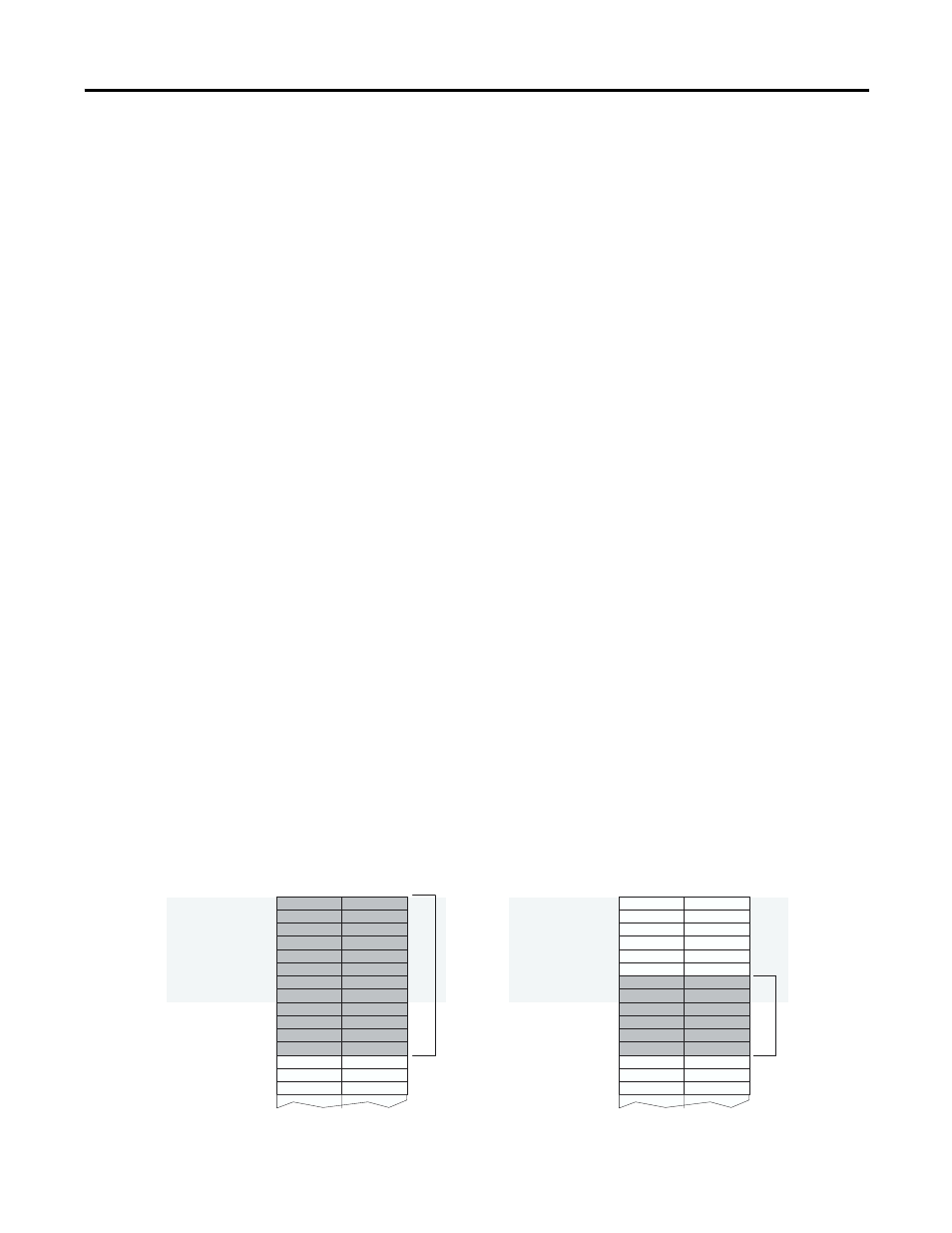
Examples 1 and 2 that follow show adapters with logical image sizes
that cross logical racks 0 and 1. The image size of the adapter in
example 1 consumes all of logical rack 0 (eight logical groups) and
half of logical rack 1 (four logical groups). The image size of the
adapter in example 2 consumes two groups in logical rack 0 and four
groups in logical rack 1.
0
7
8
15
0
7
8
15
Example 1 – Scanner Input or Output Image
Example 2 – Scanner Input or Output Image
Adapter
Image
Adapter
Image
Adapter image is 12 logical groups in size and
crosses a logical rack boundary due to its size.
Adapter image is 6 logical groups in size and crosses a logical
rack boundary due to its starting logical group number.
Group 0
Group 1
Group 2
Group 3
Group 4
Group 5
Group 6
Group 7
Group 0
Group 1
Group 2
Group 3
Group 4
Group 5
Group 6
Logical
Rack 0
Logical
Rack 1
Logical
Rack 0
Logical
Rack 1
Group 0
Group 1
Group 2
Group 3
Group 4
Group 5
Group 6
Group 7
Group 0
Group 1
Group 2
Group 3
Group 4
Group 5
Group 6
Group 7
Group 7