Rockwell Automation 1747-BSN Backup Scanner Module User Manual
Page 115
Publication 1747-UM010B-EN-P - September 2003
RIO Block Transfer 7-3
RIO Block Transfer Theory of Operation-Block Transfer Read (BTR)
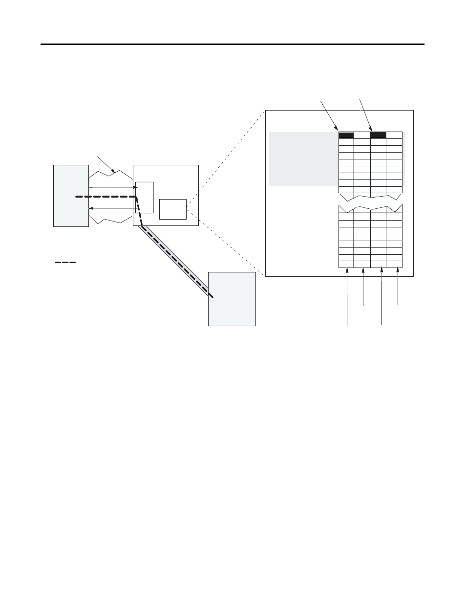
The steps below detail a successful Block Transfer Read (BTR):
1. The M0 file contains BTR control information which controls
(initiates) the scanner BTR operation. (Refer to the Block
Transfer Buffer Layout section for details on control
information.)
2. The SLC control program initiates a block transfer read by
commanding the scanner to perform the read operation. The
adapter/intelligent I/O module sends BTR data across the RIO
link to the RIO scanner.
3. The scanner writes the BTR data to a unique M1 file location
that you specify. Also, one byte of the scanner’s I/O image file
is used for "handshake" purposes between the scanner and the
adapter/intelligent I/O module. Note that the SLC control
program must never read or write to this "handshake" image
space.
In this example, Logical Rack 0, Logical Group 0, Logical Slot 1 is used.
One byte is consumed from the input and output images file for "handshake" purposes.
Chassis Backplane
I/O
Image
1747 RIO
Scanner
M
Files
RIO Link
Adapter or
Intelligent I/O
Module
SLC 5/02
(or above)
Processor
M0 file
M1 file
= path of the BTR
Input Image
Output Image
Slot 1
Slot 0
Slot 1
Slot 0
Logical
Rack 0
Logical
Rack 3
Group 0
Group 1
Group 2
Group 3
Group 4
Group 5
Group 6
Group 7
Group 0
Group 1
Group 7
Group 0
Group 1
Group 2
Group 3
Group 4
Group 5
Group 6
Group 7
Word 0
Word 1
Word 2
Word 3
Word 4
Word 5
Word 6
Word 7
Word 8
Word 9
Word 23
Word 24
Word 25
Word 26
Word 27
Word 28
Word 29
Word 30
Word 31