Rockwell Automation 1747-BSN Backup Scanner Module User Manual
Page 17
Publication 1747-UM010B-EN-P - September 2003
Overview 1-3
The SLC processor transfers the scanner’s 4 logical racks (32 input
image and 32 output image words) of discrete remote I/O image data
into the SLC input and output image files. You can adjust the size of
the scanner input and output image file during configuration of your
SLC system so that the scanner only transfers the discrete I/O data
your application program requires. Configuration is done through the
configuration file (G file). Refer to Chapter 5, Configuration and
Programming, for more information.
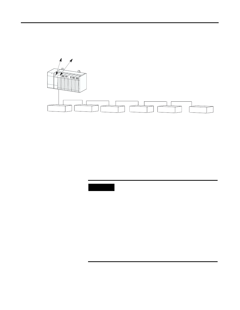
SLC 5/02 or
Later Processor RIO Scanner
The scanner transfers discrete input and output data between
itself, remote adapters, and the SLC processor. Remote
adapters consist of 1746 chassis and other Allen-Bradley
operator interface and control devices.
Half Logical
Rack
Device
Quarter Logical
Rack
Device
Half
Logical Rack
Device
Three Quarter
Logical Rack
Device
Full
Logical Rack
Device
Full
Logical Rack
Device
Adapter 1
Adapter 2
Adapter 3
Adapter 4
Adapter 5
Adapter 6
IMPORTANT
The SLC 500 processor (SLC 5/02 or later) supports
multiple backup scanners in its local I/O chassis.
The maximum number is dependent on the
following:
•
backplane power requirements
(power supply dependent)
•
SLC 500 processor I/O data table limit
(4,096 I/O)
Based on SLC processor I/O capacity only, a
maximum of eight scanners may be used when
no local I/O exists.
•
processor memory to support the application
(SLC 500 processor dependent)