How the backup scanner scans remote i/o, Backup scanner i/o image division -4, How the backup scanner scans remote i/o -4 – Rockwell Automation 1747-BSN Backup Scanner Module User Manual
Page 18: Backup scanner i/o image division
Publication 1747-UM010B-EN-P - September 2003
1-4 Overview
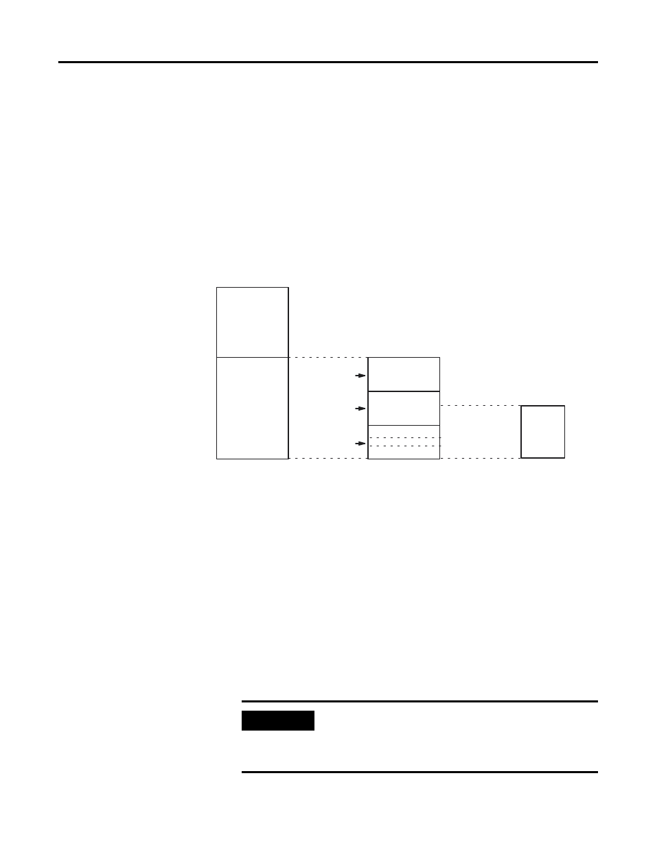
Backup Scanner I/O Image Division
The backup scanner allows each adapter to use a fixed amount
(user-defined) of the scanner’s input and output image. Part of the SLC
processor’s image is used by local I/O; the other portion is used by
the scanner for remote I/O.
The scanner’s remote I/O image is divided into logical racks and
further divided into logical groups. A full logical rack consists of eight
input and eight output image words. A logical group consists of one
input and one output word in a logical rack. Each logical group is
assigned a number from 0 to 7.
The scanner image contains the image of each adapter on the RIO
link. The adapter is assigned a portion of the scanner image, which is
referred to as the adapter image.
How the Backup Scanner
Scans Remote I/O
The scanner communicates with each logical device in a sequential
fashion. First, the scanner initiates communication with a device by
sending output data to the device. The device responds by sending its
input data back to the scanner, as illustrated below. You refer to this
exchange as a discrete I/O transfer. After the scanner completes its
discrete I/O transfer with the last configured network device, it begins
another discrete I/O transfer with the first device.
Local I/O
Remote I/O
Logical Rack 0
Logical Rack 1
Logical Rack 2
Scanner I/O Image
Logical Group 0
Logical Group 7
Adapter Image
Processor I/O Image
IMPORTANT
The scanner transfers RIO data on a logical device
basis not on an adapter basis. A logical device is a
full logical rack or portion of a logical rack assigned
to an adapter.